Hey guys, I guess I could say I am a relative newbie to the world of electronics. I have soldered many audio kits with no issues and am running a couple right now. I seem to be having an issue with the following setup though:
I have the following 2 kits:
NE5532 Preamp Kit
TDA2030A 2.1 Kit, basically two single TDA2030A's for front left and right, and a pair of TDA2030A's "bridged?" for the subwoofer. Also has NE5532 active filtering for low pass for the subwoofer.
Powered by the following transformer:
24V W/center tap 1.5 Amp Transformer
With the above setup, it runs great except I feel that 1.5A transformer gets a little too warm because it doesn't have enough power (amps). So I decided to upgrade to this transformer:
Triad F-187U 28VCT 4 Amp Transformer
It was purchased by a well known and respected vendor, Steve @ Apex Jr. He is baffled that it doesn't work, says it is new but didn't get a chance to test it before shipping, since it was new. One of the supports was bent, and I clipped off the leads shorter to remove any tarnish in case of poor contact. It looks like it has seen some years on the shelf (maybe they all look like that, IDK), but other than that looks new, even came in original box. I trust Steve, he is an excellent guy to work with.
For some reason, when I hook the new 4 Amp-28VCT trafo up, I get a lot of pops at about half the volume of the old 24VCT 1.5 Amp transformer. I can "just" hear it before it distorts. So I hooked the 1.5 Amp back up, runs great once again (I originally had it like that for almost a month with no issues whatsoever). Tried all of the above 3 times, same deal each time. I checked the newer one with a voltmeter, and with no load it reads around 30 VCT, 14.8 V per output. The older one reads 13.6V per output (27VCT ballpark).
Could the newer trafo be bad? It seems to not be putting out enough amperage possibly?? Is there any way to test it with just a couple of voltmeters, as that is all I have at the moment? Surely that extra 1-2volts +/- wouldn't do this, would it....??? The active filtering on the 2.1 setup along with the entire NE5532 preamp have voltage regulators, +-12V and +-15V respectively, and and am I correct in the chips should be OK with that voltage?
I can give more info/details to the best of my ability when I get home later today/tomorrow.
Thanks for any help/suggestions.
Nah, this kit doesn't need a pre, I just wanted to add one since this is a low budget build for my PC. Therefore, I currently eliminated it from the equation. Still have the same problem.
I'm having issues with my camera right now, got a couple of pics to come thru, let me know what else you need and I'll try to get more pics of it.
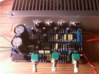
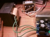
The 1st one is of my PC sub, the 2nd one is the 2.1 Amp, the 3rd is the Triad trafo hooked to the amp alongside the MCI 1.5 Amp transformer for size comparison or whatnot (no, it is not hooked up too).
I'm having issues with my camera right now, got a couple of pics to come thru, let me know what else you need and I'll try to get more pics of it.
The 1st one is of my PC sub, the 2nd one is the 2.1 Amp, the 3rd is the Triad trafo hooked to the amp alongside the MCI 1.5 Amp transformer for size comparison or whatnot (no, it is not hooked up too).
Attachments

Last edited:
Professor:
The closest thing I have is 5.4 Ohm in the 5 Watt variety, the only 6.8R resistors I own are in 1/4 Watt. Do you think the 5 watts are close enough for a short timespan?
Edit: I also have a pair of 1.5 ohm resistors of the 5W, could series them in with the 5.4 to give me 6.9R (Ballpark, they are 5%), if you think the 5W are safe enough.
Last edited:
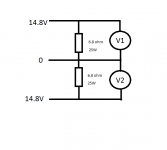
6.9 ohm is Ok but with 5W you need operate quickly or use heatsink or put resistors in a cup with water. Another way use fan.Professor:
The closest thing I have is 5.4 Ohm in the 5 Watt variety, the only 6.8R resistors I own are in 1/4 Watt. Do you think the 5 watts are close enough for a short timespan?
Edit: I also have a pair of 1.5 ohm resistors of the 5W, could series them in with the 5.4 to give me 6.9R (Ballpark, they are 5%), if you think the 5W are safe enough.
OK, just went ahead and did it super quick as the resistors heated up rather quickly, the voltage readings are 14.4V per output. If I am correct, this seems OK but wish I had some higher wattage resistors to let it sit a little while longer.
Now I'm really stumped.
Oh, I measured a pair and it read 6.7 ohms.
Now I'm really stumped.
Oh, I measured a pair and it read 6.7 ohms.
I think your transformer good. With 50% load output voltage drop on 0.4 volts.OK, just went ahead and did it super quick as the resistors heated up rather quickly, the voltage readings are 14.4V per output. If I am correct, this seems OK but wish I had some higher wattage resistors to let it sit a little while longer.
Now I'm really stumped.
Oh, I measured a pair and it read 6.7 ohms.
Last edited:
I think your transformer good.
Yeah, me too. I just got another 2.1 kit in the mail a couple days ago, I may try and solder that one up this weekend and see if I have the same problem.
Other than that, I'm still open for suggestions. I just don't understand how the weaker trafo is more powerful than the stronger one.
After A/B-ing the 2 so much yesterday, I even notice a little more bass with the weaker trafo at the same volume level.
Well I learned a valuable lesson today.
Note To Self:
Keep your workspace clean.
I've managed to ruin this kit in all this work. I was testing it without the subwoofer attached and somehow managed to get my subwoofer wires right underneath the board where the sub out is located, or somewhere in that general area. I must've crossed the two while it was on I guess, I also notice a very slight smell right against the board of a burnt IC or something. I got too confident and lazy, I always take these kits to my workbench but it's a mess full of parts right now so I did it right in front of my cumputer the last couple of times. Won't do that again.
This is only the 2nd time I've ruined a kit as I am always more careful than this. I'm so bummed right now, all I get is hum from subwoofer. The left/right produce sound, but get a hum as well. It gets really hot, really fast too.
I know I have the other kit, but this really didn't make my day, and it's early lol. Until I get more room to work I ain't touching anything for a while, so I gotta get to cleaning.
Thanks you so much for bearing with me Professor. I have to admit that I am enjoying learning about electronics, good or bad, and I kinda like the troubleshooting. Gotta learn somehow, right?
The TDA can take max 18 VDC. How much DC do you really have?
Not for sure yet, if you do the math I have around +-20 to 21 VDC. I thought these were closer to +-22VDC? I know I'm really close which is why I beefed up my heatsink a little (Thanks Steve).
I'll hook it to my PSU and get some accurate measurements thru it with my voltmeter .
Having seen Peranders warning, I thought I should look at the datasheet.
It is clearly shown that maximum Vs+ + |Vs-| must be less than 36Vdc
It is also clearly shown that all the graphs show performance upto +-16V (32Vdc).
The specification is generally using +-14V (28Vdc).
a 12+12Vac takes this chipamp very close to it's operating limits.
A high regulation transformer is likely to overload the chipamp.
A higher voltage transformer, eg. 14+14Vac is likely to blow up this chipamp.
Did you read the datasheet?
Did you download it?
Having seen Peranders warning, I thought I should look at the datasheet.
It is clearly shown that maximum Vs+ + |Vs-| must be less than 36Vdc
It is also clearly shown that all the graphs show performance upto +-16V (32Vdc).
The specification is generally using +-14V (28Vdc).
a 12+12Vac takes this chipamp very close to it's operating limits.
A high regulation transformer is likely to overload the chipamp.
A higher voltage transformer, eg. 14+14Vac is likely to blow up this chipamp.
Did you read the datasheet?
Did you download it?
I have the TDA2030A datasheet, don't know what you see that I don't but I see +-22V absolute max rating. Could you send me your copy, or a link to your copy? I'll do another search, but here is mine, take your pick:
TDA2030A Datasheet pdf - 18W HI-FI AMPLIFIER AND 35W DRIVER - ST Microelectronics
- Status
- This old topic is closed. If you want to reopen this topic, contact a moderator using the "Report Post" button.
- Home
- Amplifiers
- Chip Amps
- Trafo bad, or am I bad