How can i permanantly remove those standby and mute from TDA 7294 Bridge Amp circuit ? I read somewhere in this forum to connect pins 3 and 9 directly to positive supply and in other post it is mentioned to leave pins 3 and 9 as open (NC ). So which method is correct ?
Sunny.
Sunny.
Cable pin9 from amp1 to amp2
Cable pin10 from amp1 to amp2
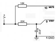
On one amp, power up the mute, pin 10, with a 10k resistor.
On one amp, power up the standby, pin 9 with a 20k resistor--To avoid a loud noise at power-up, cause that 20k resistor to charge up a 22uF cap for a delay on feature.
See also:
http://www.svet-el.si/download/Brutus 170W-S ang.pdf <--- bridge amp for 8 ohm and 16 ohm speakers
and
http://www.st.com/stonline/books/pdf/docs/1057.pdf <--- CHIP MANUFACTURER'S DATASHEET
As ST explains, the standby and mute pins (9 and 10) need voltage but Not too much current. Therefore, the minimum investment to operate mute and standby is a resistor.
Cable pin10 from amp1 to amp2
On one amp, power up the mute, pin 10, with a 10k resistor.
On one amp, power up the standby, pin 9 with a 20k resistor--To avoid a loud noise at power-up, cause that 20k resistor to charge up a 22uF cap for a delay on feature.
See also:
http://www.svet-el.si/download/Brutus 170W-S ang.pdf <--- bridge amp for 8 ohm and 16 ohm speakers
and
http://www.st.com/stonline/books/pdf/docs/1057.pdf <--- CHIP MANUFACTURER'S DATASHEET
As ST explains, the standby and mute pins (9 and 10) need voltage but Not too much current. Therefore, the minimum investment to operate mute and standby is a resistor.
wire the standby and mute pin to be permanently inactive. This prevents the standby function operating and prevents the mute function operating.
You are being short sighted, you will find why these two functions were included by the manufacturer after you have deactivated them
You are being short sighted, you will find why these two functions were included by the manufacturer after you have deactivated them
I just finished building this bridge amplifier.I connected like this:
Cable pin9 from amp1 to amp2 and connected directly to +ve supply without any resistor.
Cable pin10 from amp1 to amp2 and connected directly to +ve supply without any resistor.
Now is there any harm to speaker and Chip Amp by using this connection?
Sunny
Cable pin9 from amp1 to amp2 and connected directly to +ve supply without any resistor.
Cable pin10 from amp1 to amp2 and connected directly to +ve supply without any resistor.
Now is there any harm to speaker and Chip Amp by using this connection?
Sunny
I just finished building this bridge amplifier.I connected like this:
Cable pin9 from amp1 to amp2 and connected directly to +ve supply without any resistor.
Cable pin10 from amp1 to amp2 and connected directly to +ve supply without any resistor.
Now is there any harm to speaker and Chip Amp by using this connection?
Sunny
Yes, that's harmful--too much current! ONE event of load protect will draw all current and break loose inside.
 Click here and read ---> http://www.st.com/stonline/books/pdf/docs/1057.pdf
Why do it wrong on purpose?
Doing it right takes only 3 more parts.
20k resistor and 20uF cap for standby (pin or cable)
10k resistor for mute (pin or cable)
P.S.
If you don't want mute and standby inside your chip then buy a different chip!
The datasheet spec is to use 10k and 20k pull-up resistors (connected to PS+) as posted earlier.
The chip might get damaged because of no current limiting under some conditions...maybe...dunno.
By the sound of comments made already, the mute and standby/delayed start up are there for good reason....to avoid thumps and screams out of your speakers during power up/power down.
Datasheets are published for good reason....start reading them.
Eric.
http://www.st.com/stonline/books/pdf/docs/1057.pdf
Figure 17: Single Signal ST-BY/MUTE Control Circuit......PAGE 17.
Eric.
Figure 17: Single Signal ST-BY/MUTE Control Circuit......PAGE 17.
Eric.
ok,now i've connected standby pins 9 of both chips with 22k resistor and 22uf capacitor to +ve supply.
Mute pins 10 of both chips are connected to +ve supply through 10k resistor. Is this ok?
Sunny.
10k from V+ to mute
22k from V+ to standby
22uF from standby to ground
Clarification:
The 22k powers up both the standby pin and 22uF cap.
What type of Mute/standby switch to be used for TDA 7294 Bridge amp. As per the data sheet,only one connection is provided for both standby/mute functions.Is this push to on or push to off switch? or normal on and off switch ?
Can i use single switch for both standby and mute?Please clarify.
Thanks,
Sunny.
Can i use single switch for both standby and mute?Please clarify.
Thanks,
Sunny.
Hi Friends,
I'm still under confusion regarding Standby and mute functions of TDA 7294 Bridge amp.Some of you mentioned that connecting standby and mute pins directly to +ve supply may damage the chip amps,but i came across this circuit using TDA 7293,here is the link link where standby and mute pins
are directly connected to +ve supply without using standby/mute switch:
Project 127
please clarify.
Thanks,
Sunny
Last edited:
Some (not all) Counterfeit fake chips need more current into mute and standby pins.
Try 4.7k resistors for both mute and standby.
Its a shame that the clever people who make the fake chips don't have their own brand name and their own datasheets. Its frustrating because the parts are different than original. Usually, there are durability problems. Bridge mode is contra-indicated. Fake chips need parallel mode instead. Good luck.
Consider adding a speaker protection kit.
Last edited:
Congrats on getting the standby feature working!! Let's solve the mute problem. With a counterfeit, chip, we're going to have to find a working resistor value.
So, make these attempts in the order listed:
Try 4.7k for mute and if no sound then
Try 2.2k for mute and if no sound then
Try 1k for mute and if no sound then
Try 500Rk for mute and if no sound then
Try 220R for mute and if no sound then
Try 100R for mute and if no sound then
Try 47R for mute and if no sound then
Try 22R for mute and if no sound then
Try 10R for mute and if no sound then
Try 4.7R for mute and if no sound then
Try 2.2R for mute and if no sound then
Try 1R for mute and if no sound then
If nothing else works, omit resistor, and add speaker protector.
Good luck in getting the mystery chip to work.
Yes, the mute and standby resistors allow the amplifier to pass signal.does mute,standby resistors have any effect on the sound output ?
Yes, the mute and standby resistors allow the amplifier to pass signal.
I mean is there any any decrease in the output volume for different values of resistors used for mute ?
Sunny
Daniel,
Thanks for the solution. I tried connecting mute pin through 100 ohms resistor,now the amplifier is working.
Now is this safe?and does mute,standby resistors have any effect on the sound output ?
Sunny.
If that's about the minimum current that can run the mute, then its as safe as possible and still yet work.
The circuit that you've used doesn't necessarily affect the sound output.
However, its important to keep noises away from all pins.
Its "very rare" to get a resistor value that's borderline on-off to spontaneously active mute/standby. Sending just a bit more current through the resistor (use next step resistor value) will stop that problem with TDA7294 and LM3886.
Usually an "accidentally switch" occurs if the rails sag under the heavy load of powering 4 ohm speakers. It can also happen when using an insufficient power source (current) and/or when using unusually low voltage.
- Status
- This old topic is closed. If you want to reopen this topic, contact a moderator using the "Report Post" button.
- Home
- Amplifiers
- Chip Amps
- How can i remove standby and mute from TDA 7294 ?