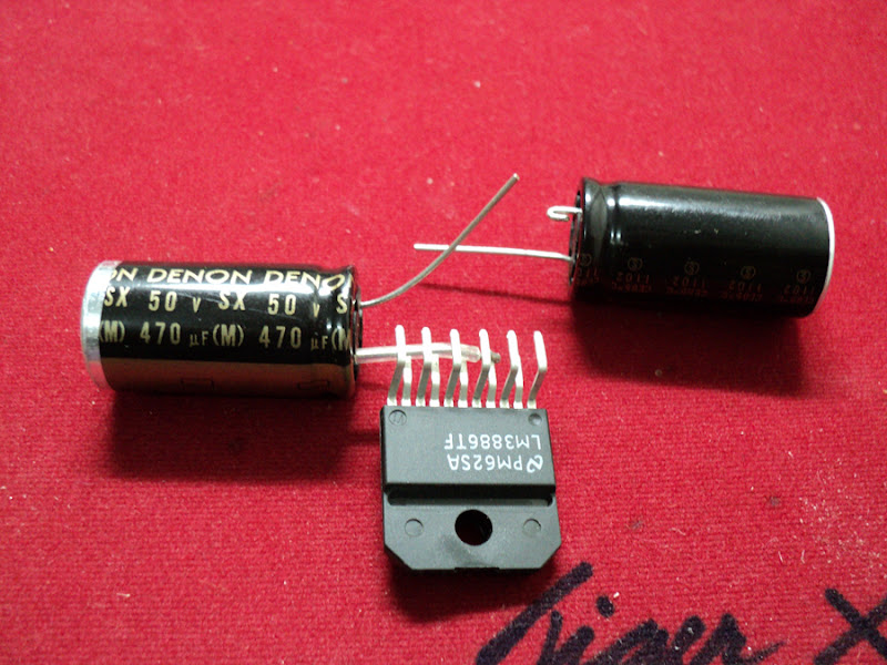
I was perusing the local electronics surplus store and saw that they had a handful of LM3886 in the bins, and thought it might be fun to wire up a pair and see how they do.
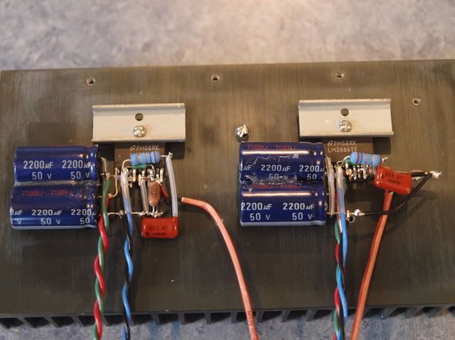
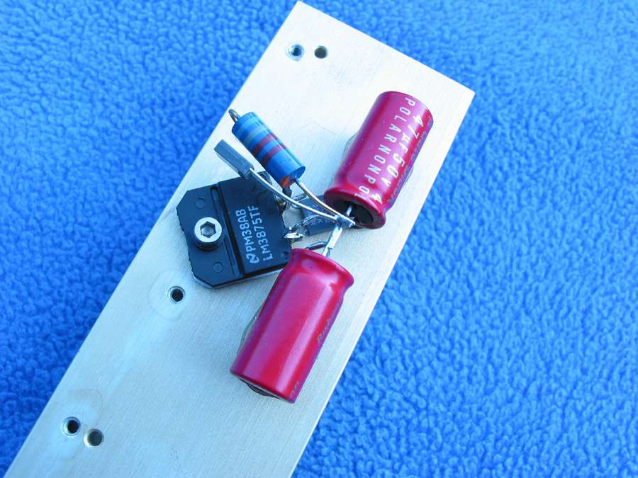
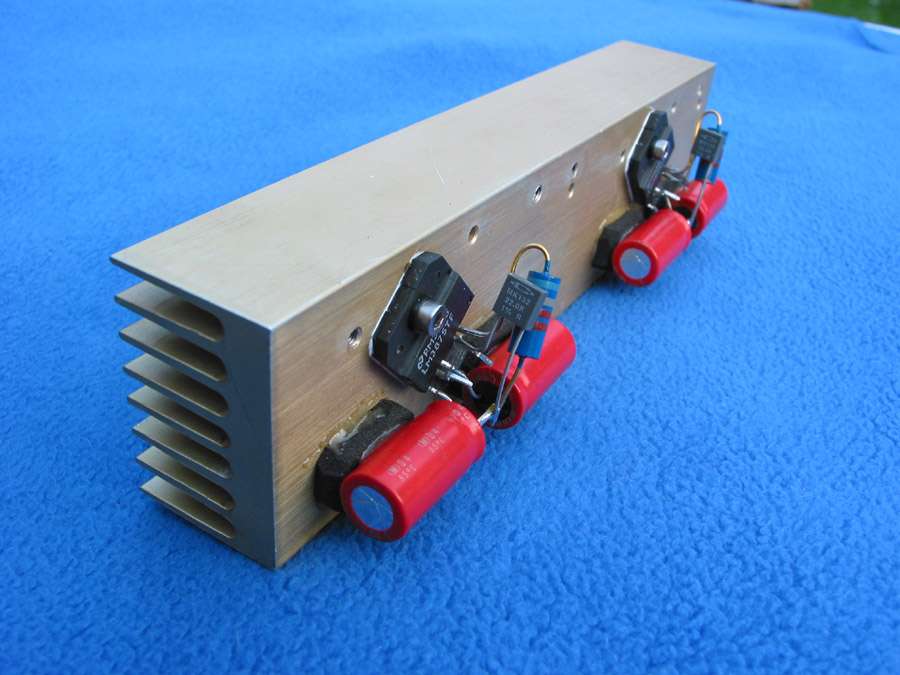
Here they are, on a heatsink used as an assembly jig.
Wires are;
Red/Green = (V+) and (V-)
Blue/Black = Speaker (+) and (-)
Orange = input twisted pair
Ground to PSU not wired.
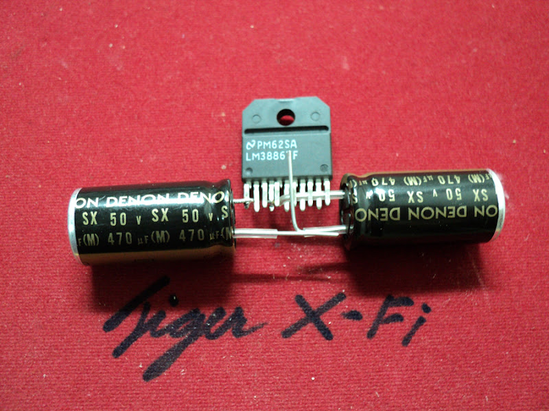
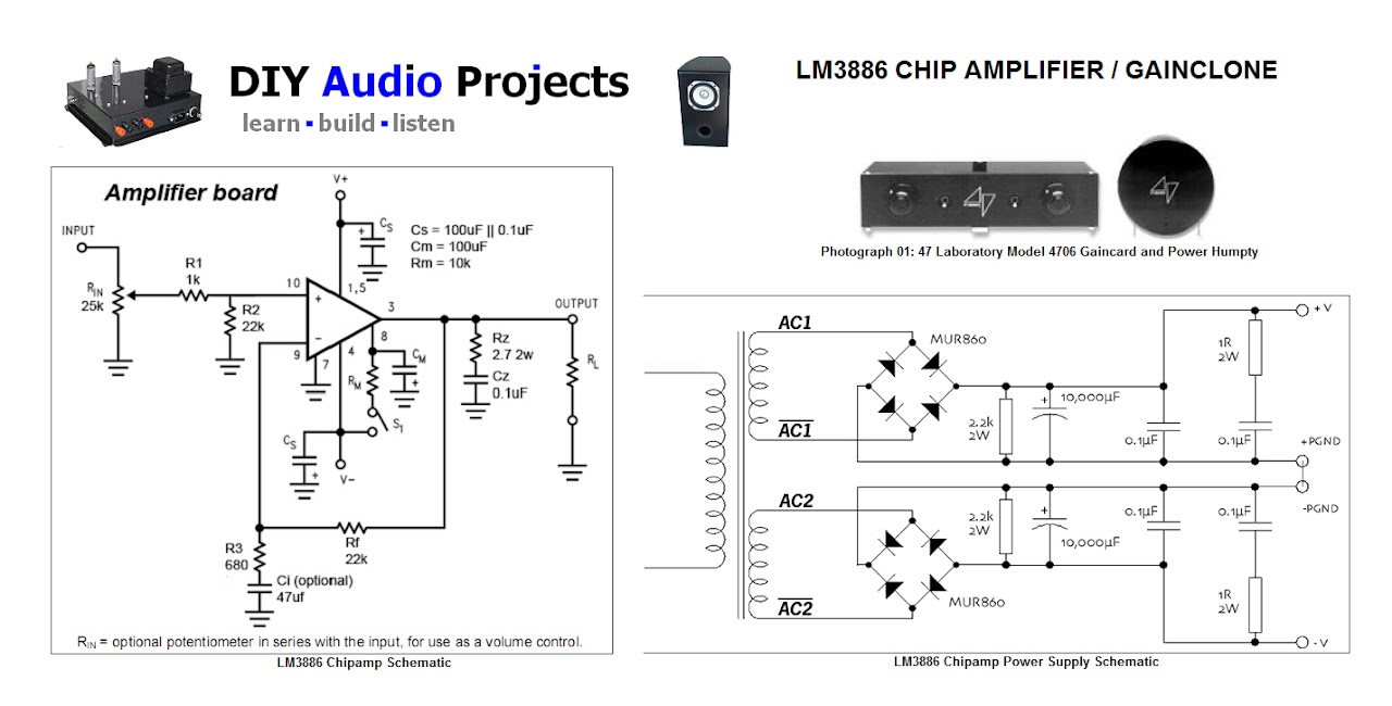
Starting with this article as a reference -- Mick Feuerbacher Audio Projects --
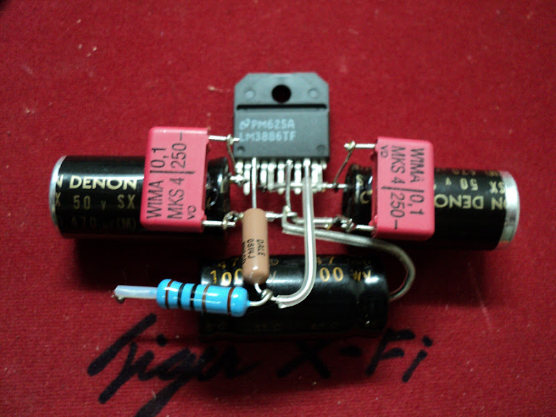
I began to wire the chips up. It's a very nice layout, but I realized, a bit too late, that when it's all done, it really is expecting to have the input RCA very close and at the right of the assembly... Hence why this one has the grounds going out that way.
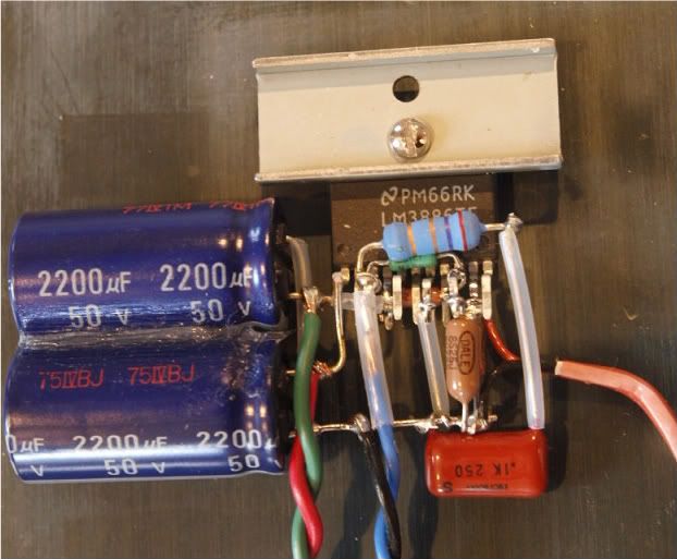
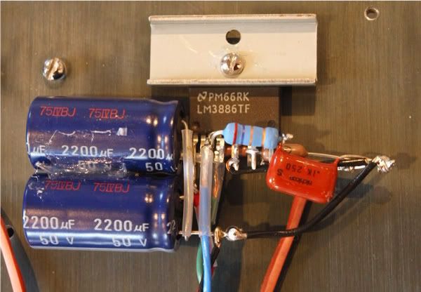
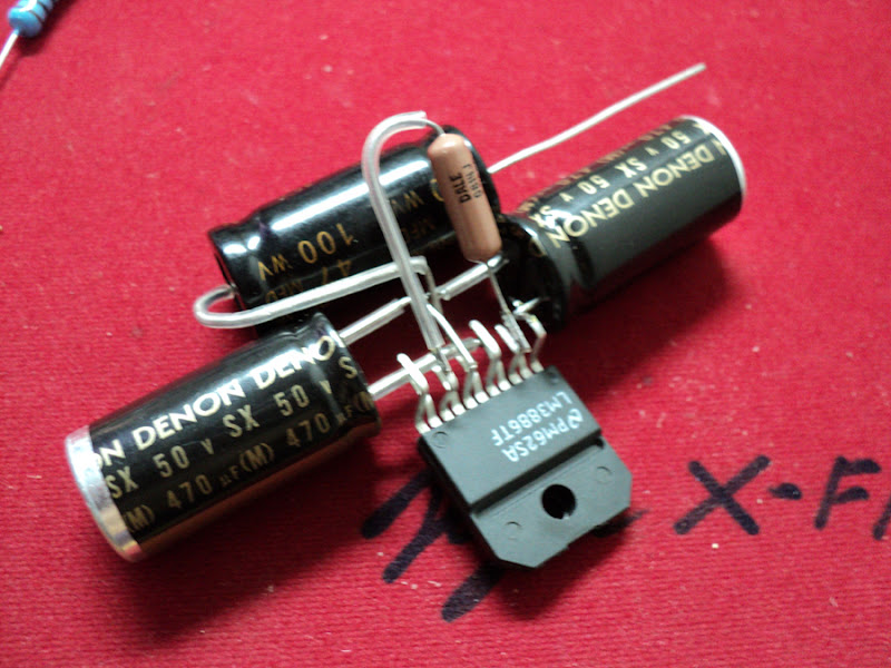
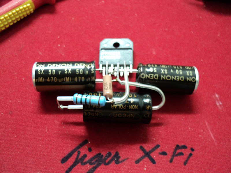
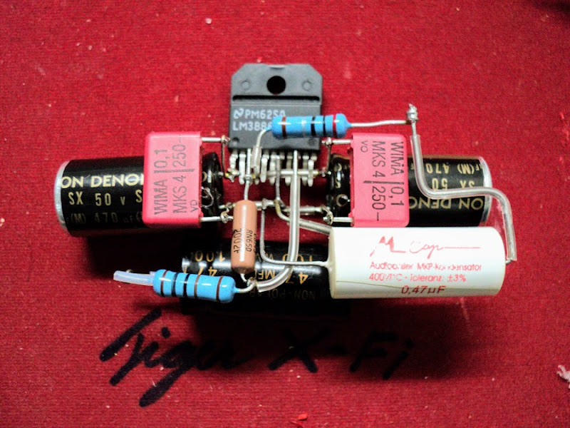
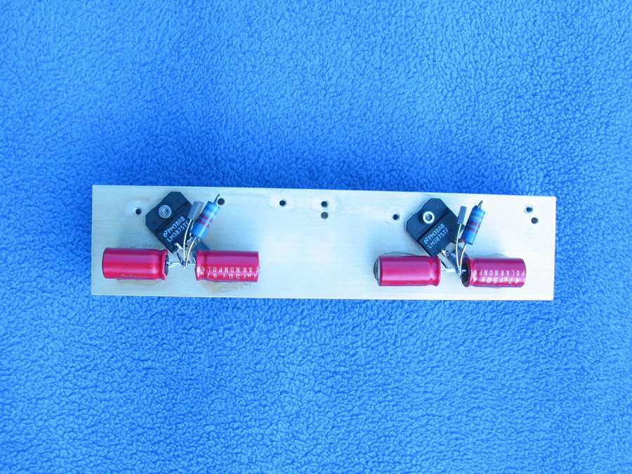
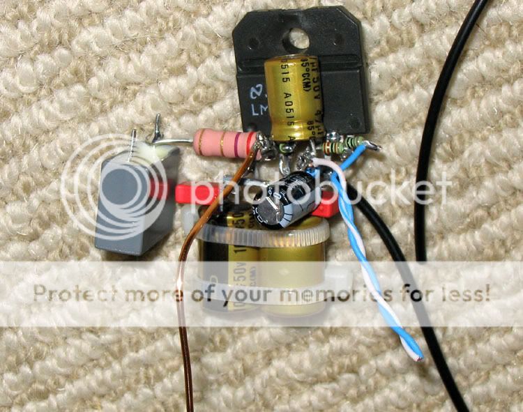
So I thought that a more vertical arrangement might yield a more compact layout, and it did. Luckily, I was able to use one of the capacitor's leads as the ground. Neat! These have the output Zobel. There is no input cap as wired, I will probably attach those to the potentiometer.
The caps are glued together with a bit of silicone, not hot glue. If small film bypasses are necessary, there is room to attach them to the electrolytics.
I have yet to build a powersupply, so these are untested.
Here they are, on a heatsink used as an assembly jig.
Wires are;
Red/Green = (V+) and (V-)
Blue/Black = Speaker (+) and (-)
Orange = input twisted pair
Ground to PSU not wired.
Starting with this article as a reference -- Mick Feuerbacher Audio Projects --
I began to wire the chips up. It's a very nice layout, but I realized, a bit too late, that when it's all done, it really is expecting to have the input RCA very close and at the right of the assembly... Hence why this one has the grounds going out that way.
So I thought that a more vertical arrangement might yield a more compact layout, and it did. Luckily, I was able to use one of the capacitor's leads as the ground. Neat! These have the output Zobel. There is no input cap as wired, I will probably attach those to the potentiometer.
The caps are glued together with a bit of silicone, not hot glue. If small film bypasses are necessary, there is room to attach them to the electrolytics.
I have yet to build a powersupply, so these are untested.
Last edited:
Looks good (Note that didn't check against the schematic), but I have a couple suggestions: Wire the signal grounds so their ground doesn't have to travel through the output return ground. I would add a couple film caps across the PSU rails. Put a thermal insulator between the big caps and the heat sink so they don't get too warm.
If you tinker around, I'm just curious at what PS voltage these chips turn on. The TDA2050 will work with a +/- 2 volt supply at a few milliwatts of output, of course.
If you tinker around, I'm just curious at what PS voltage these chips turn on. The TDA2050 will work with a +/- 2 volt supply at a few milliwatts of output, of course.
Last edited:
I did something like that except...
I made a small PC board with round pads (one for each pin) surface mount style. All the components are mounted on the circuit board with only 1 wire going to each pin of the LM3886.
That way if 1 blows up its not such a nightmare to change.
I was pleasantly surprised when it didn't feedback from stray coupling.
I do this

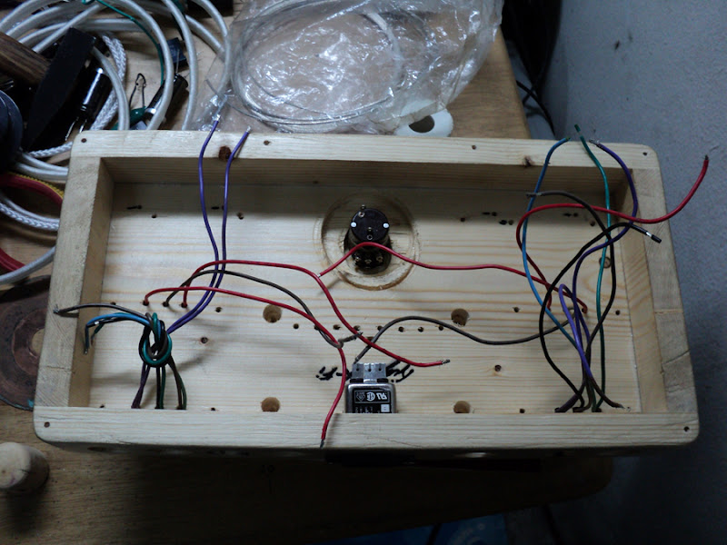
อัพเดทหน่อย
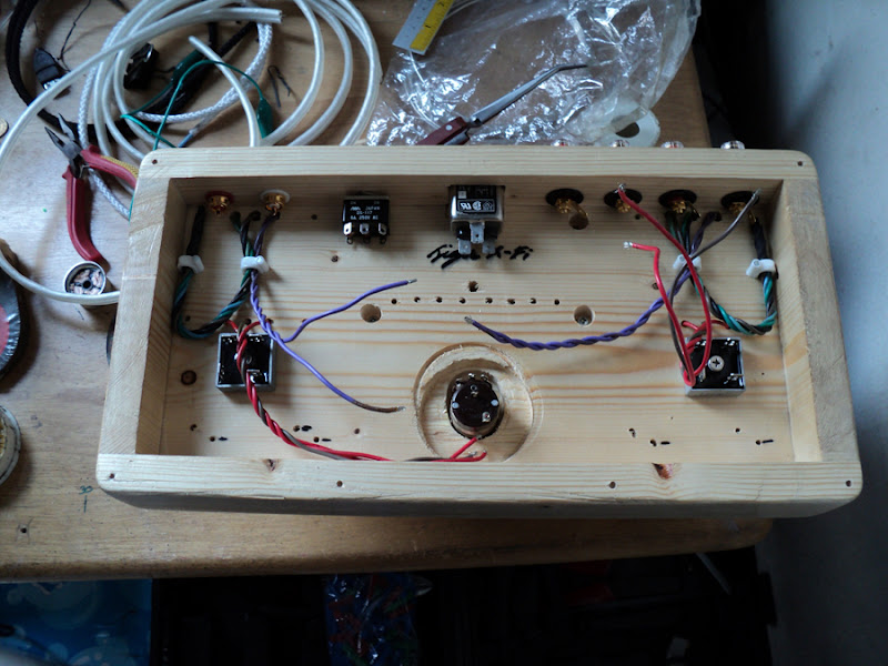
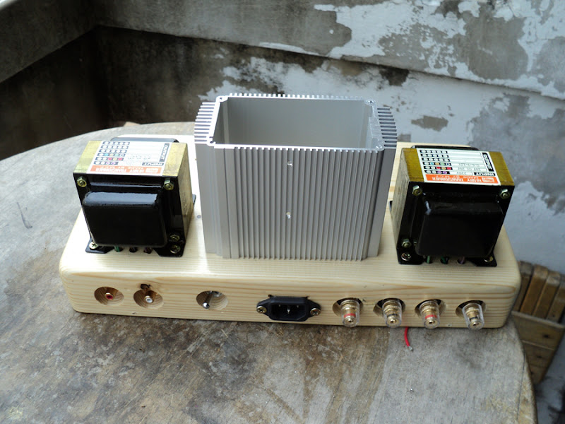
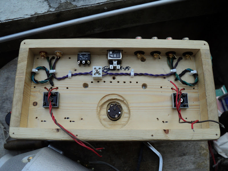


An externally hosted image should be here but it was not working when we last tested it.
An externally hosted image should be here but it was not working when we last tested it.
An externally hosted image should be here but it was not working when we last tested it.
An externally hosted image should be here but it was not working when we last tested it.
อัพเดทหน่อย
^
Oh ... Thank you very much.
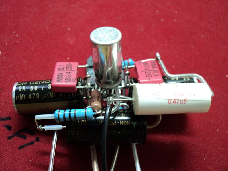
I'm coppy this schematic
Modified set of the new power supply.
Modified set of schematic chipamp.
Rin Rl cut out
Cs 470uf.
Rm 22k.
Cm 220uf.
Cz 0.47uf.
CS//0.1 uF (wima).
for balance of electric (+ -)
----
I want to use accessory to a minimum,
I'm try removing the 0.1 uF (wima) out,
Result from the electric not balance.
Oh ... Thank you very much.
I'm coppy this schematic
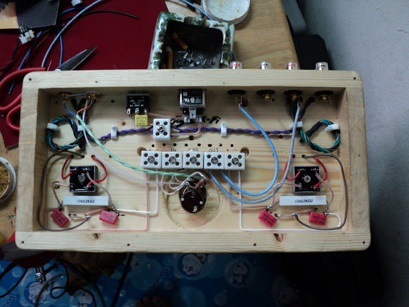
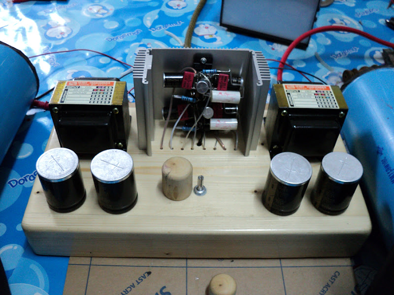
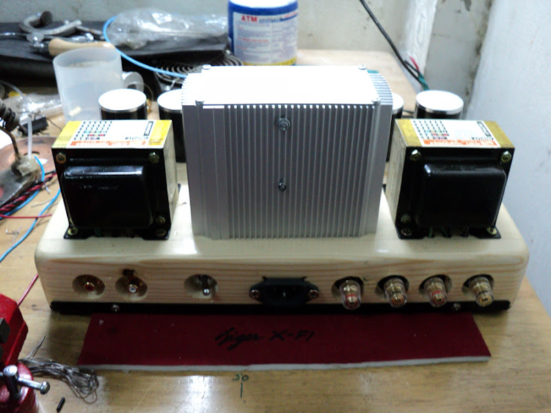
Modified set of the new power supply.
Modified set of schematic chipamp.
Rin Rl cut out
Cs 470uf.
Rm 22k.
Cm 220uf.
Cz 0.47uf.
CS//0.1 uF (wima).
for balance of electric (+ -)
----
I want to use accessory to a minimum,
I'm try removing the 0.1 uF (wima) out,
Result from the electric not balance.
Last edited:
zygibajt - Very nice so far!! I am looking forward to seeing how you make the rest of the connections.
TheLaw117 - The blue caps are no-name that I got at the local surplus store. Sorry I don't have any more information... But something like this Digi-Key - P5187-ND (Manufacturer - ECA-1HM222) would be equivalent, and about the same size.
TheLaw117 - The blue caps are no-name that I got at the local surplus store. Sorry I don't have any more information... But something like this Digi-Key - P5187-ND (Manufacturer - ECA-1HM222) would be equivalent, and about the same size.
Hi 6L6 looking good ") I'll second what Johnr66 said about separating your signal ground, if you would like to see how I did a p2p LM3886 check out my blog entry's.
I'll second what Johnr66 said about separating your signal ground, if you would like to see how I did a p2p LM3886 check out my blog entry's.
http://www.diyaudio.com/forums/blogs/wintermute/134-construction-p2p-lm3886-gainclone-part-1.html
http://www.diyaudio.com/forums/blogs/wintermute/135-construction-p2p-lm3886-gainclone-part-2.html
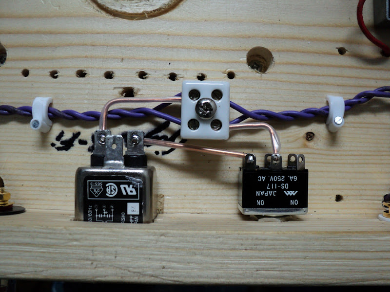
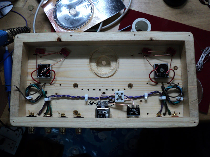
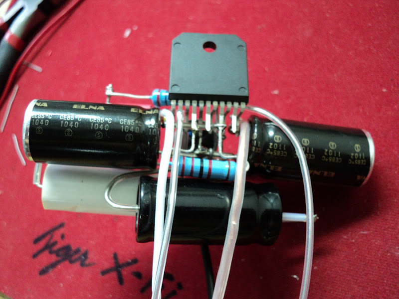
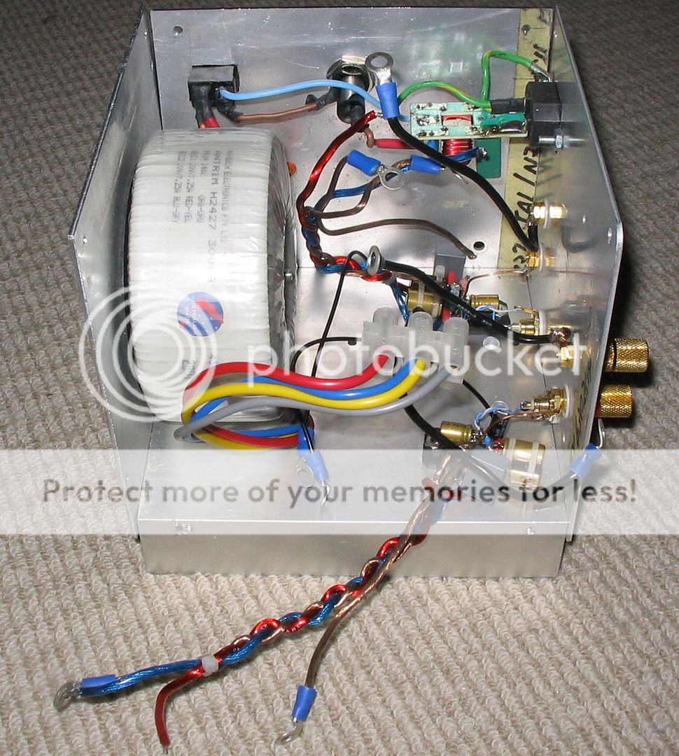
I took compactness to the extreme, which basically means it is a one off build and modifying anything is pretty much out of the question.
In total (counting speaker-return) I ended up with four separate ground connections back to the star point.
These were main power zero volts. signal, zobel cap, and speaker return.
pic to give an idea
basically I was trying to keep all connections as short as possible
Tony.
I'll second what Johnr66 said about separating your signal ground, if you would like to see how I did a p2p LM3886 check out my blog entry's. http://www.diyaudio.com/forums/blogs/wintermute/134-construction-p2p-lm3886-gainclone-part-1.html
http://www.diyaudio.com/forums/blogs/wintermute/135-construction-p2p-lm3886-gainclone-part-2.html
I took compactness to the extreme, which basically means it is a one off build and modifying anything is pretty much out of the question.
In total (counting speaker-return) I ended up with four separate ground connections back to the star point.
These were main power zero volts. signal, zobel cap, and speaker return.
pic to give an idea
basically I was trying to keep all connections as short as possible
Tony.
Last edited:
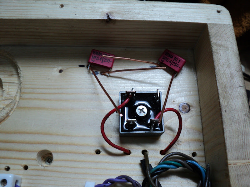
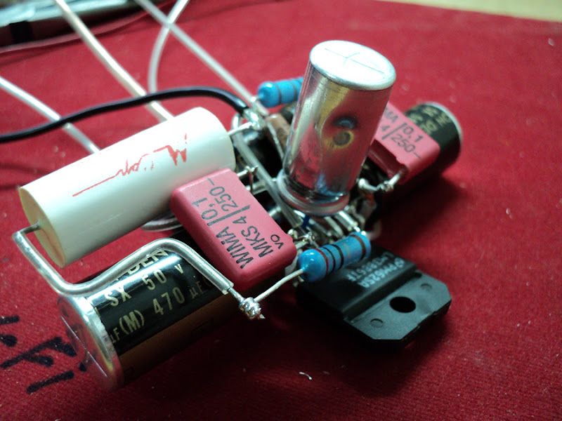
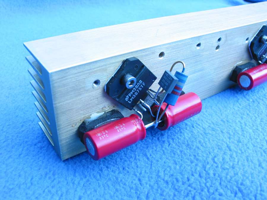
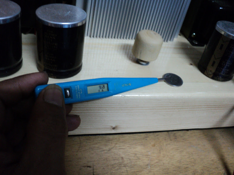
Hmmm good point quikie22, something I never even considered.... I've never run it with the cover off so not sure how warm the electros get. The heatsink under normal use barely gets warm, if pushed hard it might get up to around 40degrees C.
It's been in daily use for about a year without any sign of problems, but longevity may be an issue.
next time it has been working hard I might pull off a side cover and check the temp of the caps. I think the two main power caps are 85 deg as well, not sure about the mute cap the one closest to the chip is the NFB cap.
Tony.
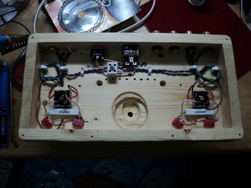
Hi Tigersilver, you would be surprised... Moving the transformer makes absolutely no difference to the noise levels, it is almost completely silent already (so much so that only the slightest his can be heard with my ear against the tweeter, and I can't reliably tell if there is any noise coming from the woofer with my ear right against it. This post http://www.diyaudio.com/forums/powe...ing-challenge-please-help-14.html#post2519106 Shows some objective measurements.
There is a very small amount of hum on the output (which the scope can pick up) but I do not believe it is radiated from the transformer. I expected to have problems with such a compact layout but was pleasantly surprised
Tony.
There is a very small amount of hum on the output (which the scope can pick up) but I do not believe it is radiated from the transformer. I expected to have problems with such a compact layout but was pleasantly surprised
Tony.
- Status
- This old topic is closed. If you want to reopen this topic, contact a moderator using the "Report Post" button.
- Home
- Amplifiers
- Chip Amps
- Point-to-Point LM3886