Hi friends,
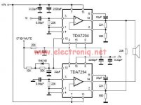
I'm interested in building this 150watts Sub woofer amplifier using two TDA 7294 chipamps.I need low frequency response starting from 10Hz.I have few questions about this amp circuit diagram(attached),please clarify.
1.What should be the value of the input capacitor connected to pin 3 to get frequency response of 10Hz? (value given as 0.5uf in the circuit).Can I use polyster or electrolytic capacitor(polarized)?
2.What should be the value of the capacitor connected between pin numbers 6 and 14 to have frequency response 10HZ(value given as 22uf in the circuit).
3.Can i use disc ceramic or polyster type capcitors for (0.22uf) connected to +ve and-ve supply lines?
4. I don't need mute or stanby features.I just wan't the amplifier switched on instantly without any mute or stanby functions. For this should i leave the connections pins 10 and 9 open on both chips or connect both pins 10 and 9 to the positive supply line?
Please help.
Thanks,
Sunny.
Attachments
Last edited:
150W bridge with two TDA7294 is wishful thinking.
That said, the input and feedback capacitor can be calculated using f= 1/(2*Pi*R*C) with selected pole frequency, with two values known the third will be known too.
For bootstrap, about 200uf should be good but IIRC the tendency to pop increases with larger values. For subwoofer application electrolytics should be fine. Amplifier will not function if mute and standby are left open. Bypass caps can be either poly or electro I don't think there is much difference.
Good Luck.
Hi Sangram,150W bridge with two TDA7294 is wishful thinking.
That said, the input and feedback capacitor can be calculated using f= 1/(2*Pi*R*C) with selected pole frequency, with two values known the third will be known too.
For bootstrap, about 200uf should be good but IIRC the tendency to pop increases with larger values. For subwoofer application electrolytics should be fine. Amplifier will not function if mute and standby are left open. Bypass caps can be either poly or electro I don't think there is much difference.
Good Luck.
Thanks for answering the questions.Can i use 1.5 uf polyster capacitor at the input and also across the pin3 of the second chip?Can i use 220 uf electrolytic capacitor for bootstrap? Please let me know how to disable mute and standby options?
Thanks,
Sunny.
10 should be good for subsonic frequencies and won't cost much.
220 should be good for bootstrap.
You cannot disable mute and standby. A simple resistor to each will avoid the delay but they need to see a small voltage on the pin to operate.
Build it, and report back.
Good Luck.
220 should be good for bootstrap.
You cannot disable mute and standby. A simple resistor to each will avoid the delay but they need to see a small voltage on the pin to operate.
Build it, and report back.
Good Luck.
check ur chips i had that problem b4 and when i replaced the 2 tda with new ones they worked finehai
i have use two tda7294 bridge circuit but it canot worked,the circuit out put is very low volume will be deliverd,then we increasing the volume the output is very low sound.so please send the solution
- Status
- This old topic is closed. If you want to reopen this topic, contact a moderator using the "Report Post" button.
- Home
- Amplifiers
- Chip Amps
- TDA 7294 Bridge amplifier Questions