For STK4048II, you can use http://www.analog.com/static/imported-files/data_sheets/AD8610_8620.pdf A Jfet input buffer That buffer wants regulators.
STK4048II wants a buffered potentiometer (not a preamp).
That's because STK4048II doesn't want increased gain.
STK4048II "K-series" should make a nice project.
---
For STK1352, you can use a discrete section as listed in this STK datasheet: http://www.datasheetcatalog.org/datasheet/sanyo/STK3122.pdf See the test circuit? Keep scrolling down and you'll see this chip is a "Driver Chip"
STK1352 contains a tiny scrap of a discrete amplifier and then you assemble the rest. . . from discontinued, fake, substitute and "OEM" remake parts. That doesn't really make much sense. Just a few minutes saved on soldering at the cost of an unstable amp?? I wouldn't do it.
Instead. . .
I'd use a new driver chip that doesn't take discontinued parts (just search for "Driver Chip," here on the forums)
-or-
I'd use a discrete solid state amplifier that comes in kit form so there's no frustrating shopping experience searching for the little bits. A few additional minutes of soldering later and you have the real deal.
Thank you for reply...Daniel, I guess. Now, I am talking about STK3152, not 1352... and sorry if I called it "preamp", yes it is driver, or voltage amp. In regards to STK4048II, are you able to post diagram of what you ment as input buffered potentiometer and how it connects to 4048...the site you suggested I couldn't open, neede some particular reader that my pc don't support at the moment...
Regards Tom
Regards Tom
Sorry for the previous typo. I had meant to type 3152. . .
The datasheet listed above for 3122 is correct because its in the same family of chips. Your 3152 is the higher voltage version of the 3122 driver chip. The spot to post questions about driver chips is the "Solid State" forum, since the labor and parts to use a driver chip is 2/3rds of a discrete amp.
EDIT: I must assume that 3152, although intended as a driver chip, must also be able to operate as a phase split, an op-amp and a preamp; however, the term "driver chip" is simply more specific.
.
PDF reader software--its vital. . .
For opening PDF type files, popular readers include Adobe and Foxit. During installation, I'd personally choose "custom" and deny / disable the installation of any extraneous toolbars.
You will really really need to have a PDF reader installed in order to make use of electronics data-sheets. Its unnecessary to pay for that software, because some of it is available open source.
Last edited:
..one more question, what if I use bipolar buffer...
A buffer isn't required by non-inverting amplifiers like yours.
A bipolar buffer, in this case, is extraneous or redundant
A 6n3p buffer might be useful but its application specific
A jfet buffer is mostly likely to be useful in general purpose
The datasheet linked above, is AD8620, a quality jfet op-amp (specific mention of "buffer" by the manufacturer indicates Unity Stable), and there is some expectation to power it from regulators for clean operation. Perhaps a separate little enclosure would make it easier to apply. Many models of Unity Stable Jfet Op-Amp are available.
The main task of the buffer is to prevent audible problems in applying potentiometers. That's why I mentioned earlier to buffer the potentiometer. Its risky to say it this way, but here goes: The buffer is for the potentiometer, not for the amp.
More specific:
If Not using a Unity Stable Jfet Op-Amp, then don't add a buffer and don't add a preamp, because. . . non-specific add-ons would be extraneous.
P.S. See the Decibel Dungeon site and Rod Elliot's site for examples of jfet buffers and volume controls.
Thank you for your reply again. I am now working on the design of PC board for 4048, using Protel. First time doing something like that but hope I will get there. As you mentioned that 4848 doesnt like preamps, what kind of signal level is acceptable on its input.
I did look a bit through the subject of buffers an I would like to try a tube aproach. There are tubes like ECC86, which can work on low ( 12 - 24V) voltage. Is it sensible aproach?
I did look a bit through the subject of buffers an I would like to try a tube aproach. There are tubes like ECC86, which can work on low ( 12 - 24V) voltage. Is it sensible aproach?
The STK4048 already specs considerable gain. Its not allergic to preamps.
However, a buffer is more suitable. . . because a buffer has zero gain.
I cannot answer your question about tubes for general purpose buffer use although I have used some tubes for application specific harmonic filters. For better information, see the tube section of diyaudio.com.
Again, please bear in mind that STK4048 doesn't require either a preamp or a buffer.
Thanks for opinion. I am working on pcb now, but I noticed discrapencies between original SANYO schematic for 4048XI and PCB that they suggested. Would you be able to look at that and try clarify? On their PCB pin 9 is connected to C8, which is in series with C5 which goes to pin7. But on schematic joint point between C8 and C5 is also connected to pin10?
Also there are two unused pads, between R8 and C5...seams like possible link to cross the track, but that would actualy cause short between pins 7 and 14...
Thank you, Tom
Also there are two unused pads, between R8 and C5...seams like possible link to cross the track, but that would actualy cause short between pins 7 and 14...
Thank you, Tom
Download | Datasheet Archive
and
Download | Datasheet Archive
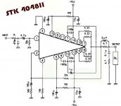
Looking at "Application Circuit for STK4048II" schematic will be more accurate than any wordy description that I could provide.
and
Download | Datasheet Archive
Looking at "Application Circuit for STK4048II" schematic will be more accurate than any wordy description that I could provide.
Attachments
Last edited:
. . .Also there are two unused pads, between R8 and C5...seams like possible link to cross the track, but that would actualy cause short between pins 7 and 14...
. . .
We don't normally put random jumpers between all of the extra pads on various circuit boards. I'm sorry if that sounds rude. Its just a generalization.
Clues
Sorry that I couldn't find out about the variance in datasheets for pins 8 and 11. Some datasheets favored an RC, but other datasheets favored not using pins 8 and 11.
This difference occurs in "Application Circuit"
The STK4048II doesn't use pins 8 and 11
The STK4048V has the RC
All versions have the RC for "Testing Circuit"
So, I couldn't figure out whether to use the pins 8 and 11 RC or not. I hope you have a scope or some pertinent (pins 8 and 11) information from other STK4048II (STK4046II, STK4050II) users.
The determining factor "might be" the internal "Equivalent Circuit" that shows the internal transistors. The STK4048II is a simpler design than STK4048V.
Other information is mentioned in this thread:
http://www.diyaudio.com/forums/chip-amps/3500-stk-chips.html#post32025 <---link
Particularly interesting are the stability tips. They're applicable to the longevity of STK 4046, 4048 and 4050. Higher stability generally "makes room" in all other tolerances, usually leading to higher performance, at your option. The thread documents a high performance amplifier, able to amplify all observable audio aspects in correct proportion.
P.S.
So, the only thing I found out about internal differences is that the internal design of STK4048II looks like the type that would perform better if using capacitive multiplier power or regulated power. It looks a bit sensitive and could favor some "pampering" at the parts of the circuit that are under your control. That's generally true of most audio amplifiers.
The difference between STK4048II versus a discrete solid state amp, is that the STK is sealed up. You could just have a look at the equivalent circuit and compare that to projects in the discrete solid state forum.
Here is new dilema!!
I have got hand on two STK4048XI "K" series. For curiosity I decided to do some measurement. According to SANYO equivalent circuit, output is complementary type. Pins 7,13,14,17 are connected to NPN type transistors, and pins 10,12,16,18 to PNP type. So between pins 7 and 14 multimeter is showing around 0.7V, which is ok as it is passing through only one junction; BUT then between 7 and 13, as well as 7 and 17, I am still reading 0.7V, even that there are two junctions between pins.
On PNP side, between pin 10 and 12 is 0.7V, while between 10 and 16, as well as 10 and 18 is 1.2V, which I was expecting.
Is ther something I dont know, or something is wrong?
Will appreciate help.
Regards,
Tom
4048 is a very simple "blameless"
4048 has very high gain with the app note values +55db (does not need a preamp).
Circuit is the same as a "entry level" blameless/lin amp (below 1)
Dan is right , pin 5/15 could be run with separate supply/ cap multiplier.
Pin 4 could be 6.8k/22uf/6.8k to ground for 6-10db more PSRR (better separation).
In general , chip is way overrated (150w my butt) 100-120w is more realistic.
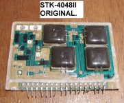
being a cascoded VAS design , it would also suffer "droop" with a 4R load. Be nice to this poor little chip. Real pix (below 2).
It would be 2 times the size of a 4048 + testboard as a drawback.
OS
4048 has very high gain with the app note values +55db (does not need a preamp).
Circuit is the same as a "entry level" blameless/lin amp (below 1)
Dan is right , pin 5/15 could be run with separate supply/ cap multiplier.
Pin 4 could be 6.8k/22uf/6.8k to ground for 6-10db more PSRR (better separation).
In general , chip is way overrated (150w my butt) 100-120w is more realistic.
being a cascoded VAS design , it would also suffer "droop" with a 4R load. Be nice to this poor little chip. Real pix (below 2).
Much more than that , equivalent 4 OP device discrete amp would TOTALLY decimate this chip in both sound quality,power and durability.The difference between STK4048II versus a discrete solid state amp, is that the STK is sealed up.
It would be 2 times the size of a 4048 + testboard as a drawback.
OS
Attachments
Last edited:
Thank you Daniel for comments, and to you Ostripper too. I would just like to mention that you are both talking constantly about 4048II, while I am about 4048XI. They are significantly different if you look at their diagrams. Ostripper, the diagram you have inclosed is actualy 4048XI, not 4048II.
I have designed my PCB, wait for it to be made, then I will be able to tell some results.
And, yes, Daniel, that previous thred by Rljones ( Robert) was very good work with 4048XI; he tested it in bridge configuration and claims 190W/8 using +/-33V. According to him, 300W/8 could be expected with +/- 49V. I am looking forward to my PCB.
Regards,
Tom
And, yes, Daniel, that previous thred by Rljones ( Robert) was very good work with 4048XI; he tested it in bridge configuration and claims 190W/8 using +/-33V. According to him, 300W/8 could be expected with +/- 49V. I am looking forward to my PCB.
Regards,
Tom
If we used a 56vct meaning 28,0,28VAC transformer for about 41VDC rails, we get very close to ABS max current handling on your bridge amp with 8 ohm speakers.
Its good to know maximums so that we can avoid using them.
- Status
- This old topic is closed. If you want to reopen this topic, contact a moderator using the "Report Post" button.
- Home
- Amplifiers
- Chip Amps
- Connecting STK hibryds...