OPA541AP can use +/-35 volt supply. Gain bandwidth 1.8 MHz
It delivers 50 Watt into 8 Ohm at gain=20
THD is low. 0.002%
But upper bandwidth we get is 'only' 90 kHz
OPA445AP is a DIL8 package opamp that can take +/-45 volt supply
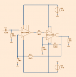
If we use OPA445AP at gain=20 and attach OPA541AP as buffer output
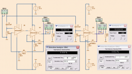
we get a combo with very good performance. Tiny THD distortion at 50 Watt.
Image 1. Shows a compare of THD at 50 Watt RMS into 8 Ohm
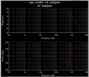
Image 2. Shows compare of AC, Combo vs. single OPA541
The upper bandwidth is ~500kHz vs. ~90kHz
It is possible to do like this with a normal opamp,
but then with dual supplies. One for buffer and one for opamp.
This combo uses only one supply +/- 35 VDC
It delivers 50 Watt into 8 Ohm at gain=20
THD is low. 0.002%
But upper bandwidth we get is 'only' 90 kHz
OPA445AP is a DIL8 package opamp that can take +/-45 volt supply
If we use OPA445AP at gain=20 and attach OPA541AP as buffer output
we get a combo with very good performance. Tiny THD distortion at 50 Watt.
Image 1. Shows a compare of THD at 50 Watt RMS into 8 Ohm
Image 2. Shows compare of AC, Combo vs. single OPA541
The upper bandwidth is ~500kHz vs. ~90kHz
It is possible to do like this with a normal opamp,
but then with dual supplies. One for buffer and one for opamp.
This combo uses only one supply +/- 35 VDC
Attachments
2nd low V supply lets you use better input op amps, at only a few 10 mA you can use Zener shunt supplies for the +/-12-15 V input op amp supply - and by sub regulating you get better psrr too
more op amp choices, better perfromance only pennies added cost, or savings if lower V op amp is cheaper than opa445 (digikey wants US$11.8 in singles) - I think I'd go for "less simple"
more op amp choices, better perfromance only pennies added cost, or savings if lower V op amp is cheaper than opa445 (digikey wants US$11.8 in singles) - I think I'd go for "less simple"
Last edited:
probably yes, but you couldnt expect the same performance
OK. Question from ignorance here.
I have not previously run across the OPA541AP I downloaded a data sheet and, at first glance, it doesn't seem to be anything special. It costs AU$26.90 at Futurelec, a good supplier in OZ.
At the same supplier an LM3886 is AU$4.20.
The only standout spec is the THD which is quite a bit lower.
Is this why you suggest that the LM3886 will give inferior results?
Would make sense.
Has anybody ever used the OPA541AP as a stand alone gainclone?
How much better than a 3886 does it sound?
rgds
blakkshepeaudio
unity gain stable internal compensation also makes it easier to use 541 in a multiloop than the audio power "chip amp" LM3886/TDA7293 class parts which are only stable for gains >10-20
and despite the decompensation they have only ~2X higher GBW
for cost effectiveness it is probably worth dealing with the decompensated gain and making up any performance lack by paralleling and Class AB biasing the cheaper chip amps - more complexity for the performance even if all of the parts could be cheaper - spend money on extra heatsinking and power supply
http://www.diyaudio.com/forums/chip-amps/164634-chip-amp-rival-hi-end-design-advice.html mentions some techniques to improve chip amp performance
Last edited:
its not the only standout, as jcx mentions its far better suited for lower gain, thd as you say is considerably better and the national part has more than 10 x the input offset. theres more as well, but i dont have the time to analyze it, its obvious to someone who knows what they are looking at and really they are quite different parts, much more standalone power and higher supply voltage for the national part, where the 541 would be better suited to input driver duties and mid level power applications.
@jcx, agreed better performance for marginally more complexity could be had using a fully differential opamp like ths4131 etc, or crazy low noise unity gain stable chips like te lme49990, but i think the point here was simple power supply, simple cct, great performance
@jcx, agreed better performance for marginally more complexity could be had using a fully differential opamp like ths4131 etc, or crazy low noise unity gain stable chips like te lme49990, but i think the point here was simple power supply, simple cct, great performance
That's why I asked...
Well, now I have had a chance to have a better than 'first glance' look at the data sheet, I can certainly see numerous differences which would make this item more suitable for the circuit proposed by the OP. I have also done my homework on the OPA541AP and it's use in gainclone-style chipamps, as well as various buffer and nested fedback variations. I think I will see the obvious things for myself in the future, and may even end up knowing what I am looking at. Perhaps I might build a few and try them out. bsasnip > its obvious to someone who knows what they are looking at < snip
")
What is the modeled THD+N of the combination at 10khz and 20khz?
The buffer is slower than the op-amp on the outside. Is that the reason for R2 and R5? Will the system oscillate like AN47 page 14 describes?
If you wanted more power, you could drive the load balanced. Assuming 30 Vpk-pk and 10A limits, 112 watts into 8 ohms; voltage limited =)
The buffer is slower than the op-amp on the outside. Is that the reason for R2 and R5? Will the system oscillate like AN47 page 14 describes?
If you wanted more power, you could drive the load balanced. Assuming 30 Vpk-pk and 10A limits, 112 watts into 8 ohms; voltage limited =)
Last edited:
That is not correct.
Power = Voltage * Current.
You must use rms voltage and rms current if your are not using DC voltage and DC current.
For (all) AC signals:
P = Vrms * Irms = Vrms^2 / Rload = Irms^2 * Rload.
If you use peak voltage of a sinewave then you must account for the crest to average ratio in a sinewave.
P = Vpk * Ipk / 2 = Vpk^2 / Rload / 2 = Ipk^2 * Rload / 2.
A sinewave signal that is 15Vpk into an 8r0 load results in 15^2 / 8 /2 = 14W
Using balanced to double the load voltage results in 30^2 / 8 / 2 = 56W
that 30Vpk sinewave applied to the 8r0 load can be written as 60Vpp sinewave into 8r0 for 56W of output power.
Last edited:
- Status
- This old topic is closed. If you want to reopen this topic, contact a moderator using the "Report Post" button.
- Home
- Amplifiers
- Chip Amps
- Hifi Combo with OPA445AP + OPA541AP