Hi,
yes I have read some posts/threads about Linn chip amps.
But, having been thinking about the Chakra patent for the last couple of months
I thought it might be interesting to share my ideas and get some answers from the experts.
The idea is to "reveal" the Linn Chakra schematics.
yes I have read some posts/threads about Linn chip amps.
But, having been thinking about the Chakra patent for the last couple of months
I thought it might be interesting to share my ideas and get some answers from the experts.
The idea is to "reveal" the Linn Chakra schematics.
From LINN's whitepaper:
CHAKRA
Monolithic technology is used extensively throughout Linn’s product range, both as single chips and paralleled devices to increase power output. The CHAKRA topology is the result of more than 5 years of continuous development of Linn’s high-power monolithic amplifier audio circuits, and was initially conceived during development work for the Linn 328A professional monitoring loudspeaker. The Linn 328A required greater power, circuit density and performance than even our reference monolithic power amplifier, the KLIMAX 500 Twin, could offer, and so we began work on developing a solution which performed accurately and consistently in even the most demanding monitoring applications.
The CHAKRA topology we devised uses an array of large bi-polar transistors as ‘boosters’ around a single monolithic. This approach in itself is not a new idea, but Linn’s execution of the monolithic to bi-polar transition is truly unique, and a patent application for the design has been submitted. When output current is less than a few amps, all of the power output comes from the monolithic, maximising the speed and linear properties of this design. At higher output currents the bi-polars provide the majority of the output current, leaving the monolithic to operate well within its capability and so able to correct any error instantaneously. Even under extreme overload conditions, like short circuit, the monolithic never delivers more than a fraction of its safe output, while separate circuitry protects the bi-polars. So with current output virtually unlimited, CHAKRA offers robust and powerful low-frequency response down to near DC. This is essential for the type of servo-controlled bass systems used throughout Linn’s highest performance loudspeaker systems and benefits will extend across all future iterations and applications of the CHAKRA topology. The new topology is also very compact, actually reducing the circuit area and signal path length compared to our previous best paralleled topology and it is also highly efficient, running cooler than any previous Linn amplifier design.
POWER SUPPLIES
While the new CHAKRA topology represents a massive step forward in Linn’s direct signal path circuitry, the overall performance of a power amplifier is equally dependent on its power supply. Linn’s compact proprietary, audio-optimised Switch Mode Power Supply (SMPS) technology generates stable, low noise power rails for the audio circuitry, with higher mains noise isolation and efficiency than the very bulky and noisy conventional power supplies. The combination of SMPS and CHAKRA technologies creates a wealth of possibilities for new configurations of high-performance, high-efficiency Silent Power amplifiers.
LINN ACTIVE TECHNOLOGY
A key design consideration during development of the CHAKRA audio circuit technology was the ability to power loudspeakers in internally or externally active configurations. As a result, active modules can plug directly into the main CHAKRA amplifier for straightforward active system building. Each of these active modules filters the signal for one drive unit, with a separate module allowing simple and subtle optimisation of the system to suit the room, aiding the simple installation of active systems and optimising performance.
CONCLUSION
The Linn CHAKRA technology eliminates the weaknesses and maximises the strengths of monolithic linear amplifier technology. It combines the speed and precision of a high integration chip technology with the ruggedness and smoothness of discrete ultra-linear bipolar transistors and delivers precisely controlled Linn Silent Power at all listening levels.
If you look at the patent schematics (upload of the pictures wasn't successful, I will upload them later), there is something new about the circuit.
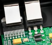
They have added some inductors "for axtending a switching off period of the second amp (with the bipolars) to smooth any switching discontinuity", as the patent says.
When you look at fotos of the Linn amps (i.e. C2200,Klimax Chakra 500) you will notice the
inducters close to the bipolar transistors.
That's the new circuit by Linn.
Klimax Chakra 500 Twin
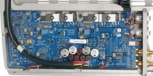
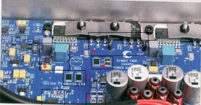
Here is a picture of the Klimax Chakra 500 TWIN prototype.
My suggestions for the marked areas are:
A. Bipolas with "Chakra" inductors (obvious)
B. OpAmp for ??? (most likely a DC-servo ? in the feedback path), you will find this in every Linn amp with Chakra circuit.
C. Sense resistors. Most likely sensing the V+ and V- current through the TDA and the bipolars. As the manual of the klimax tells us, the amp will monitor the current and will turn-off the amp in case of ultra high current. You will find this also in all Linn amps.
D. Boucherot network
E. A pair of diodes to minimize inductive backloads.
F. Most likely a quad OP-AMP. But what for ? The Klimax senses the input and turns-on when the audio input is >100µV. This quad could do this and at the same time acts as an input buffer (?).
G. This is R1 in the patent circuit.
Any other suggestions ??
Ideas and questions welcome.
Attachments
First Schematics
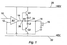
This my idea of simplified schematics for the Chakra circuit.
1. 1st stage as input buffer and low pass filter
2. TDA with OPamp in feedback path as DC offset servo (I have seen this a couple of years ago in a Burmester 878).
3. The Chakra stage withe the bipolars and the inductors.
4. The output shows the boucherot and the protector diodes.
Any mor suggestions on this ?
Kind regards
Attachments
I think the bipolars are placed differently, see http://www.diyaudio.com/forums/chip-amps/42578-about-linn-power-amps-2.html#post582631

Hi Jo!
The inductor is connected to the emitter,you are right. But the transistors could still be connected as in the other thread (but I'm not sure). They always try to hide things in patents and with the TDA7293 it really works well to put the bipolars there. Can't anyone check this on their chakra amp?
The inductor is connected to the emitter,you are right. But the transistors could still be connected as in the other thread (but I'm not sure). They always try to hide things in patents and with the TDA7293 it really works well to put the bipolars there. Can't anyone check this on their chakra amp?
Those inductors are ferrite beads.
MURATA|BL02RN2R1M2B|FILTER, EMI, 7A, RADIAL, DOUBLE | Farnell United Kingdom
MURATA|BL02RN2R1M2B|FILTER, EMI, 7A, RADIAL, DOUBLE | Farnell United Kingdom
Those inductors are ferrite beads.
Right. Probably wrapped around some copper-nickel alloy wire to replace the "ordinary" emitter resistors. Looks more like voodoo to me...
the text would lead you to believe that they developed their own chip, doesnt look like that?
Indeed that's what I thought too, looks like some ST micro chip, unless they have ST make them for them.
Looks like a simplification of the 405 current dumper to me. Back when the 405 circuit was analysed in Wireless World, I built a LF351 opamp based prototype with a pair of output transistors with no bias and single output inductor. I found that even with no bridge, feedback was enough to make this circuit work pretty well into headphone loads.
ST make power opamps, enough to drive 1V into 4R before the dumpers take over
ST make power opamps, enough to drive 1V into 4R before the dumpers take over
- Status
- This old topic is closed. If you want to reopen this topic, contact a moderator using the "Report Post" button.
- Home
- Amplifiers
- Chip Amps
- Linn Chakra power amps revealed ...