Hello,
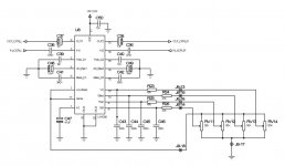
I've put together a circuit identical to that in National's Data Sheet. I get a near to 48 MHz sine wave of about 200 mV out of both outputs. This is with no input signals. I get this result with several different chips. I tried first on solderless breadboard and now on a perfboard.
The upper side of the perfboard is a ground plane where all capacitors are tied as short as possible.
I tried first with conventional components (wired) and now with SMT.
But all that without any result...
Any ideas?
Thanks!
I have been using LM1036 quite successfully on one of my amps for arnd 6 years now ! It's made on a piece of prototyping board, no noise not even any hiss. If you could post some pictures of your pcb and schematic we could figure out obvious mistakes if any,Hello,
I've put together a circuit identical to that in National's Data Sheet. I get a near to 48 MHz sine wave of about 200 mV out of both outputs. This is with no input signals. I get this result with several different chips. I tried first on solderless breadboard and now on a perfboard.
The upper side of the perfboard is a ground plane where all capacitors are tied as short as possible.
I tried first with conventional components (wired) and now with SMT.
But all that without any result...
Any ideas?
Thanks!
Thanks for your answers,
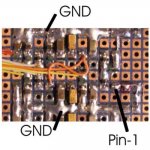
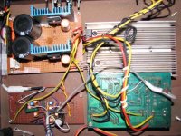
On the photo the upper and bottom strips are connected to the ground plane on the other side of the PCB.
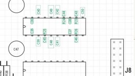
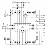
The photos are less usable...so I've drawn the layout of the SMT parts. The viewing of the drawing is from the top of the PCB. The photograph's was taken from the back.
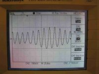
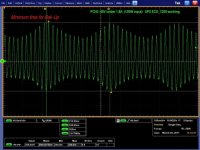
On the last picture is the waveform on the output of the LM1036.
On the photo the upper and bottom strips are connected to the ground plane on the other side of the PCB.
The photos are less usable...so I've drawn the layout of the SMT parts. The viewing of the drawing is from the top of the PCB. The photograph's was taken from the back.
On the last picture is the waveform on the output of the LM1036.
Attachments
Thanks for your answers,
On the photo the upper and bottom strips are connected to the ground plane on the other side of the PCB.
The photos are less usable...so I've drawn the layout of the SMT parts. The viewing of the drawing is from the top of the PCB. The photograph's was taken from the back.
On the last picture is the waveform on the output of the LM1036.
you are using the DIP package of the IC right ? why use smd parts on a normal prototyping board, from the way the soldering appears on the prototyping board it appears you have might have a solder bridge somewhere. If you're going to make it on a prototyping board make it with normal through hole parts it'll much less messy and chances of any shorts, solder bridges reduced.
No chance that there is any short. All has been checked with ohmmeter and capacimeter with the active components removed.
On the other side, I tried first with conventional components (through hole parts) and the results where the same.
I expected the results would be better with SMD and a ground plane on the other side.
I've use SMD cause there will be a space issue on the board when it will be fully equiped ...
Sorry if it sound a bit confused, but my english is far from perfect...
Thanks for your answer Mooly,
You can't know if I am a beginner or what may be my level of knowledge. I should say first am working in R&D, mainly in EMC (electromagnetic compatibility) since 1982 and I am confident with most of the parasitic effects that can appear.
I've already done all these tests. Power supply is clean, ground is clean, and all other ICs were removed from the PCB thanks to IC-sockets.
At work I could do more precise measurements. The base frequency varies from 44 to 47 MHz and is amplitude modulated at about 3 MHz. This wave is only on both output pins. For this measurement the pots were replaced by 10k/10k divider.
Someone had the same problem in 2003. He had left a message "Help with LM1036? " in sci.electronics.design but without any answer.
Attachments
Thanks for your answer Mooly,
No problem, I'm just at a bit of a loss what to suggest tbh.
Have you tried "rolling a finger" over the components to get some idea of what/if anything alters. Oscillation is one thing, but AM modded at 3mhz... that's a bit weird. Maybe also try a variable PSU, just to try and get a handle on what's occuring.
Last resort would be to build the circuit using point to point wiring (just to see) and check if anything odd shows then.
I have this chip too.
I made the exact circuit just like the datasheet says.
It does not work at all, I get some wieeerd noise only on outputs.
I have absolute no idea why. I did not realy care, so i just ut it on shelf.
I made -after reading you post- a new point to point constructed one, using the same chip. Same effect.
I have no idea why. I would suspect a lot of these chips are dead to be honest.
I managd to find many forums where simular complains are made, and yet none offered any solution.
-> i wrote this down only to confirm you ma had built it exactly as it should be, yet it may still not work at all.. <-
Hello Mooly,
I've rebuilt the circuit this weekend as you suggested. Powered with a battery just in case. Tried to change the value and the technology (Solid Al or tantal) of C50, C47, C48 and C49. I put a 100nF parallel to these caps. But without any improvement.
The only way to get rid over the oscillation was to put a 220pF on each output to gnd. This solution does not satisfy me too well as long I do not understand what happens exactly...
Arty,
Could you put a scope on the output to see if your problem is the same that mine ?
I have no idea why. I would suspect a lot of these chips are dead to be honest.
Its a National Semiconductor part, I find it very hard to believe it could be broken out of the box.
Could you (and daniel23) post pictures of your chips ? It might provide some clue.
Can't really offer much more advice never having used one of these. If it does it with point to point wiring where there is no possibility of strange ground effects then I'm at a bit of a loss.
Is it still the same if the inputs are grounded ? Try decoupling the "zener ref" mentioned in the data sheet... pin 17 was it !
I agree adding shunt capacitance to the outputs isn't the answer... I wouldn't be happy either.
----------------------------------------------------------------------------------------------------------
I wouldn't have thought the IC was one that would be faked... it's to specialised and of limited application.
Hello Mooly,
I've rebuilt the circuit this weekend as you suggested. Powered with a battery just in case. Tried to change the value and the technology (Solid Al or tantal) of C50, C47, C48 and C49. I put a 100nF parallel to these caps. But without any improvement.
The only way to get rid over the oscillation was to put a 220pF on each output to gnd. This solution does not satisfy me too well as long I do not understand what happens exactly...
Arty,
Could you put a scope on the output to see if your problem is the same that mine ?
I have been using the chip successfully albeit my chip was a National Sample and my schematic was out of an old elektor project "acitve pc speaker" ..I don't remember the exact title. It was published in 2004 I think. I might have a pdf of that . I will dig out the article tonight.
I tried with the inputs shorted to ground or with 10k to ground. No result.
I tried decoupling the "zener ref" with 100nF to 10uF. No result.
I tried to fit a 1k in the output in case it won't be stable with the capacitance of the scope probe directly attached. Only effect: the amplitude decreased due to low-pass 1k to input capacitance of the probe.
My hair will begin to turn to white ...
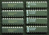
Here is a pictures of the chips as yajnaS asked. The 4 chips on the left were bought at a local reseller. The 4 chips on the right were directly bought at NS (they were shipped from Germany).
I tried decoupling the "zener ref" with 100nF to 10uF. No result.
I tried to fit a 1k in the output in case it won't be stable with the capacitance of the scope probe directly attached. Only effect: the amplitude decreased due to low-pass 1k to input capacitance of the probe.
My hair will begin to turn to white ...
Here is a pictures of the chips as yajnaS asked. The 4 chips on the left were bought at a local reseller. The 4 chips on the right were directly bought at NS (they were shipped from Germany).
Attachments
I tried with the inputs shorted to ground or with 10k to ground. No result.
I tried decoupling the "zener ref" with 100nF to 10uF. No result.
I tried to fit a 1k in the output in case it won't be stable with the capacitance of the scope probe directly attached. Only effect: the amplitude decreased due to low-pass 1k to input capacitance of the probe.
My hair will begin to turn to white ...
Here is a pictures of the chips as yajnaS asked. The 4 chips on the left were bought at a local reseller. The 4 chips on the right were directly bought at NS (they were shipped from Germany).
Although it's not very clear in my pic, but my chip looks like the ones on the left. I had ordered the samples back in 2003 I think.
I have no scope, to be honest 
I could use my soundcard, but only for AF.
After fiddling a bit with the IC, i got to the point where it acts as a radio, depending on how i set the pots.
Under no circuimstance the sound is clear, no mather what pot settings i use.
Furthermore, my tone controll pots interact with the volume too.
The volume pot does not follow the behaviour one would suspect, i mesure the controll voltage and over 4 volts, the sound gets less loud as i approach 5 volts.
I bet my IC is dead.
For kicks, i asked around a bit.
There is a KIT, many peeps are statisfied with it.
I have ordered one, and will make a photo of the PCB for you.
And allso make a schematic.
I would suspect it is the manufacturer recommended circuit, but what gives if it is not?
I did check if i accidently mixed up the controll voltage pins, but.. sadly it seems i made no mistake. The reseller of the kit usualy sells original kits, and copys of the kits on smaller boards, and different component selection. (example, larger input caps, and so on.. little improvements.)
I wrote a mail to ask about an enhanced kit version, but i was told they make no such thing, as the IC can oscillate with ease. I was usggested to use the inferior TDA chip, as it is less problematic.
I found this kinda fishy, but does not mather.
I have ordered the kit, and will do my best to provide the information i manage to get.
Hopefully we can work out something, at least i will have volume controll on my amp.
- Status
- This old topic is closed. If you want to reopen this topic, contact a moderator using the "Report Post" button.
- Home
- Amplifiers
- Chip Amps
- High frequency sine wave on the LM1036 output