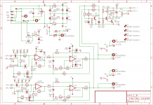
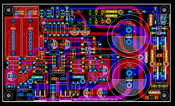
This is a first-pass attempt at building a scaled-down, value-oriented version of a nested gainclone similar to the Mauro Penasa MyRef design. It differs from the MyRef RevC in several ways:
1) LM1875 chipamp as the Howland current pump offers more component flexibility - can be interchanged with TDA2040, 2050, etc.
2) Lower output power of 20W + 20W makes it suitable for bookshelf and HT setups.
3) Two channels/board to reduce overall system costs. The board is only ~15% larger than a single MyRef RevC version 1.3 monoblock.
4) Op-amp flexibility - it will work with numerous commodity (NE5532, etc.) and premium opamps (LM4562, OPA2134, etc.) for the outer voltage-feedback loop, with slight changes in compensation in some cases.
5) Outer loop uses Walt Jung's nested schema, which differs slightly from the MyRef.
6) Compensation schema is much simpler, with a single modified DeBoo integrator per channel, greatly reducing the component count of premium capacitors compared to the RevC.
7) Speaker protection circuit is identical to the MyRef RevA 2-channel schematic.
8) Shared rectifier and PSU caps to reduce board area and costs.
I'm calling it the MyRef Mini because of its close similarity to Mauro's MyRef series. It still needs to be built and validated, but I expect it to be comparable to or better than the MyRef Rev A in audible sonics (with the components shown in the schematic). In audible sonics, it should comfortably crush the Yuanjing and similar EBay gainclones based on the LM3886, LM1875, LM4766, TDA7294, etc., at a slightly higher price point for a 2-channel board.
Here are the exported images of the Schematic and Board Layout (warning: although completed, this is only a first-pass attempt and may have undiscovered errors in both the schematic and layout). The dimensions of the PCB are about 5.5 x 3.2 inches. The BoM should be sub-$50 for the PCB and all the components on the PCB. If there's sufficient interest, I'll eventually have a small batch of bare PCBs fabricated and offered here.
Attachments
Last edited:
I believe the pad sizes are adequate, since the parts outlines are from the same library that I'm using with my current MyRef RevC version 1.3 monoblock design, which is completely validated and is currently shipping with no pad or drill size issues. However, I'll eventually re-check all the pads and drill sizes when I go through the CAM output process before handing off for PCB fabrication.
Note that this will be a DS-PTH FR4 board, designed for 35+35 micron Cu. The pads are intrinsically more hardy than single-sided, 17.5 micron Cu boards.
Note that this will be a DS-PTH FR4 board, designed for 35+35 micron Cu. The pads are intrinsically more hardy than single-sided, 17.5 micron Cu boards.
Last edited:
I believe the pad sizes are adequate, since the parts outlines are from the same library that I'm using with my current MyRef RevC version 1.3 monoblock design, which is completely validated and is currently shipping with no pad or drill size issues. However, I'll eventually re-check all the pads and drill sizes when I go through the CAM output process before handing off for PCB fabrication.
Note that this will be a DS-PTH FR4 board, designed for 35+35 micron Cu. The pads are intrinsically more hardy than single-sided, 17.5 micron Cu boards.
I had some really hard time with my pcb guy for the first set of boards I made, they too are FR4 PTH but the drill size he used for resistors and small caps was way too large and thus ate away some part of the pad, I had to waste one batch of pcb's before I learnt the lesson

I had some really hard time with my pcb guy for the first set of boards I made, they too are FR4 PTH but the drill size he used for resistors and small caps was way too large and thus ate away some part of the pad, I had to waste one batch of pcb's before I learnt the lesson
Well, tough luck. That's why you need to use a vendor with CNC drills - just specify the drill sizes in your CAM (Excellon) files and hope that the machines are correctly configured with a full set of drills in the rack.
One of my vendors has exactly the opposite problem - for small batches, he uses manual drilling, ignoring the Excellon files, and usually chooses drill sizes which are about 0.1mm smaller than specified. I now have a small batch of MyRef Rev C boards in which almost all the drill sizes are OK, *except* for a few relating to fast-on tags, which are a bit smaller than specified. I can't make my existing fast-on tags fit, and have to go and hunt for some with thinner legs. Not a show-stopper, but nevertheless an irritant.
R12=3k3 seems rather high.
Do you have a reason for adopting this value?
RC~0.7us is normal.
3k3 and 220pF are exactly the same vales in used in Mauro's Rev C, where it works fine as the input RF filter. That works out to an RC of approx. 0.7 usec, doesn't it? In practice, I sometimes use 2k7 instead, but that's not a significant difference.
Very nice. Looking forward to the test. I might be interested in a
few, to make a HT amp.
For a multi-channel HT amp setup, it might aid the layout in the chassis
if you could move the LM1875s to the width side of the PCB, kinda
where the LM3886 was located in the MyRef monoblock PCB.
few, to make a HT amp.
For a multi-channel HT amp setup, it might aid the layout in the chassis
if you could move the LM1875s to the width side of the PCB, kinda
where the LM3886 was located in the MyRef monoblock PCB.
For a multi-channel HT amp setup, it might aid the layout in the chassis
if you could move the LM1875s to the width side of the PCB, kinda
where the LM3886 was located in the MyRef monoblock PCB.
I thought about it initially, but what I've done is better for small form-factor 2-channel setups, where the chipamps can be bolted to the rear wall of the cabinet. It will even work with the Projekt X cabinets on EBay, where the largest dimension is the depth - in this case it could bolt to the side wall(s).
The other advantage of this form-factor is that the power trace lengths from the main filter caps to the chipamps is shorter and encloses less EMI radiating area for the circulating currents.
I don't understand the purpose of a redesign, and I really don't understand copping Mauro's designation. The amp, as originally designed and subsequently built by hundreds of DIY'ers, was Mauro's best personal effort, after much experimentation, at building a compact, simple, economical, reasonably powerful amplifier with excellent sound. He succeeded on every count, as many will testify. It was, indeed, his own personal reference amplifier. That's why it was called "MyRef".
Now you want to shrink it, economize it, reconfigure it, "improve" the circuitry. What is left to call it "MyRef" other than your own desire to take advantage of Mauro's considerable efforts and ingenuity and the notoriety it afforded him?
It's fine that you want to tinker with it, but then it's your baby and it should be called something else entirely. Perhaps your design will sound even better, and it will deserve its own unique designation. It is not MyRef, mini or otherwise.
Peace,
Tom E
redesign!!
thats what most people do on this forum.evenif its just a capacitor!
i think your being quite unfair to linuxguru.hes been very helpful on this forum and never shows any attitude in his posts. ibelieve he's an honest guy who wants to credit where credit due and not hanging on coat tails.
thats how things move forward , some take a leap in design (mauro rev) and that may become the new standed.take the whole gainclone scene!!
I, too, believe he's an honest guy. I also value his posts. It's precisely for those reasons that I think he should use another name for his design. He is not merely changing a capacitor (we already did plenty of that and didn't change the name!); he is changing the basic form of the amp. The only thing it still has in common with Mauro's design is the embedded opamp.
I'm not being unfair to Linuxguru at all. He can redesign anything he wants, but when it no longer resembles the original it should have its own name. I'm being fair to Mauro.
Peace,
Tom E
I'm not being unfair to Linuxguru at all. He can redesign anything he wants, but when it no longer resembles the original it should have its own name. I'm being fair to Mauro.
Peace,
Tom E
I, too, believe he's an honest guy. I also value his posts. It's precisely for those reasons that I think he should use another name for his design. He is not merely changing a capacitor (we already did plenty of that and didn't change the name!); he is changing the basic form of the amp. The only thing it still has in common with Mauro's design is the embedded opamp.
I'm not being unfair to Linuxguru at all. He can redesign anything he wants, but when it no longer resembles the original it should have its own name. I'm being fair to Mauro.
Peace,
Tom E
Hi Tom,
I'm not sure I agree. The title of the thread is what caught my attention, and I like the design. If he called it my gainclone x, I wouldn't be here discussing it
with you
It is after all a mini myref isn't it? Should the mini aleph be called Greys mini se class A?
OK, I see the point being made by Tom, and I'll concede it to him. The main issue seems to be the use of the "MyRef" name for a circuit which isn't actually the same as Mauro's original MyRef design.
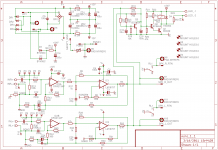
I hereby change the name of this design to "MiniRef", which more accurately reflects the fact that it is not the MyRef, although it derives/borrows numerous ideas from Mauro's MyRef design (it also uses ideas due to Brad Howland, Walt Jung, DeBoo and numerous earlier designers) . I will also make the change on the schematic and the silkscreen of the PCB, as soon as it is practical to do so and before it is fabricated (if that ever happens).
I hereby change the name of this design to "MiniRef", which more accurately reflects the fact that it is not the MyRef, although it derives/borrows numerous ideas from Mauro's MyRef design (it also uses ideas due to Brad Howland, Walt Jung, DeBoo and numerous earlier designers) . I will also make the change on the schematic and the silkscreen of the PCB, as soon as it is practical to do so and before it is fabricated (if that ever happens).
Last edited:

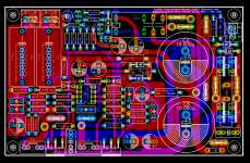
Here is the current MiniRef schematic and board layout (initial prototype version) with some layout and component changes:
1) The main PSU filter caps are now of 30mm diameter (from 35mm earlier).
2) The smaller PSU caps, along with placement optimizations, allow the board to be shrunk to 100 sq.cm. (about 15% lower than the previous version).
3) Some component values have been changed after simulation runs.
4) Slightly improved signal ground planes and shielding.
5) Drill optimizations - only 5 different drill sizes.
I have taped out the Gerbers and Excellon files, and they've been sent for fabrication of the initial prototype run - maybe 10 to 20 boards at most. There are still some unrouted airwires visible on the board layout, but they're Eagle artifacts which are not required to be routed. There may still be errors in the schematic and layout which may be discovered only after building prototypes - we'll see how it goes when the boards are delivered in ~2 weeks.
Attachments
Last edited:
- Home
- Amplifiers
- Chip Amps
- MiniRef Schematic and PCB layout