Any news?
I've been able to audition the LM3886TF/OPA2134 version with a Marantz CD63 source and 2-way, 8-ohm folded-horn towers designed by Sreekanth (the best 2-way speakers I've heard) in Bangalore. Interconnects to the speakers were also Sreekanth's braided design. Trafo was 160 VA, EI core.
The good news: It sounded very transparent, clean and dark with no trace of hum or interference. It's comparable to the MyRef on sonics, probably even more neutral.
The bad news: One channel kept going into thermal runaway, which indicates that it's probably at the edge of stability and requires changes to the compensation to increase phase margin.
So it went back to the drawing board for compensation tweaks. I made some mods (on the existing board, without any track cuts but one wire jumper) but haven't tested/auditioned it yet. I was busy with simulations of various discrete opamps over the last month - my existing LF03 discrete opamp, though stable, was current-starved and distorting in the MiniRef. There's a simple mod to the LF03 to bias it so that it draws lower current (say 8-10 mA per channel) and stays in Class-A in the MiniRef. I plan to test all these changes when I get around to the next series of tests this month.
It could be as simple as not having small bypass capacitors right at each power pin. Also, the decoupling/local reservoir capacitors seem too far from the power pins.
It could be as simple as not having small bypass capacitors right at each power pin. Also, the decoupling/local reservoir capacitors seem too far from the power pins.
You're probably correct on both counts. The distances are even more on the MyRef, which doesn't use rail-to-ground small bypasses near the LM3886 power pins, but it's likely that they're mandatory here. I just got a few Panasonic ECHU 22nF/50V SMD film caps in 1210 size, which should be perfect for bypassing in this application.
I'm very surprised that Mauro didn't use HF bypass caps. I guess I never checked. Most transistor-based amplifiers have a hidden positive HF feedback path through the power rail. Without bypass caps, it's like asking for trouble. The bypass caps need to be within a millimeter or two of each power pin.
Decoupling is another matter. The decoupling caps can be thought of as a small local power supply, to provide fast-changing transient currents on demand. So they should be as close as possible to the chipamp power pins, to minimize the impedance presented to the pins.
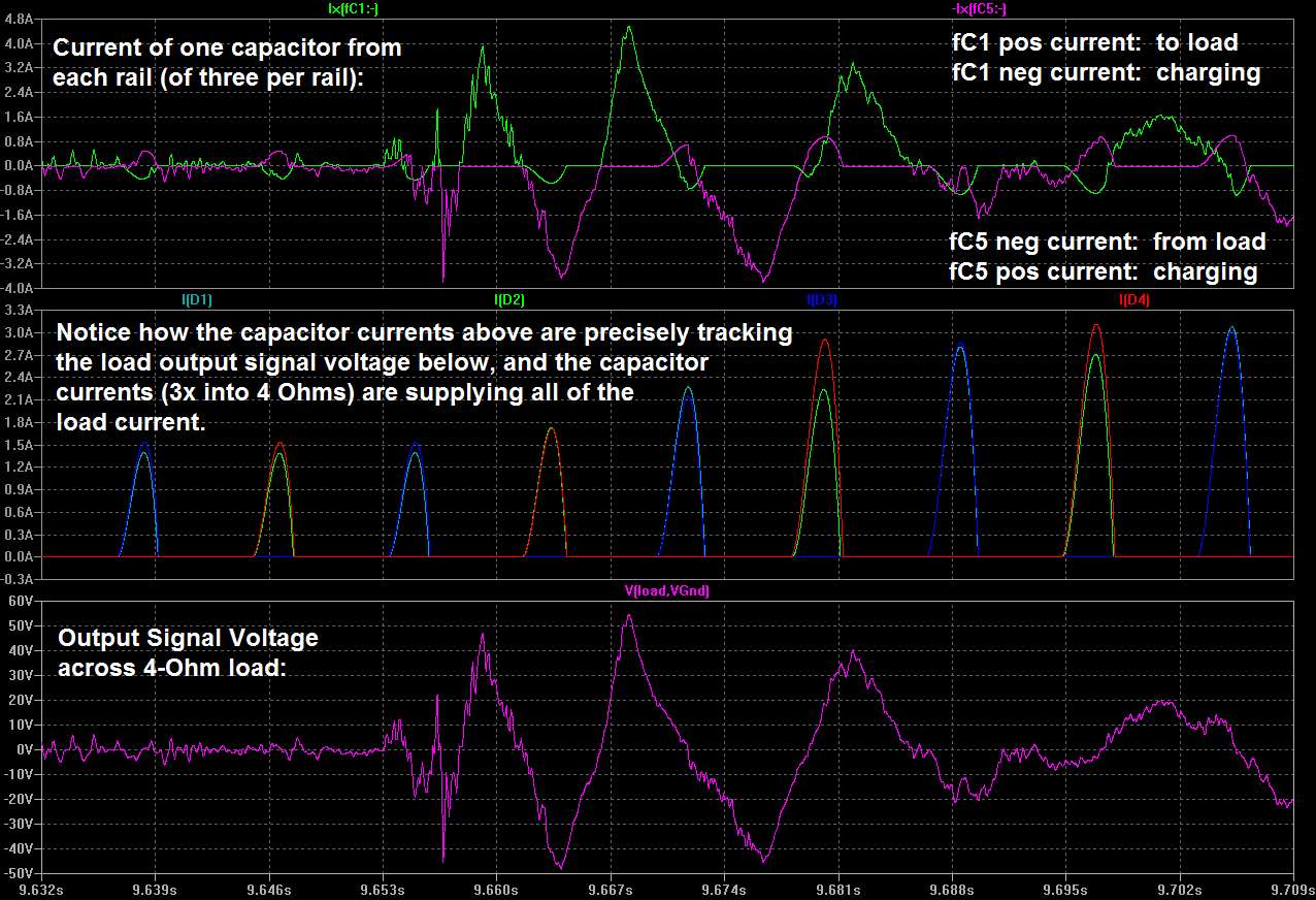
Maybe I should first say that the sound from the speakers is made by current that is almost all coming directly from the power supply and decoupling capacitors, which is modulated by the amplifier. Quite-convincing proof of that is shown in this plot: http://www.diyaudio.com/forums/atta...3-power-supply-resevoir-size-zoom3a_33kuf.jpg , which is part of a post at http://www.diyaudio.com/forums/power-supplies/216409-power-supply-resevoir-size-38.html#post3117390 .
"The rails currents ARE the signal and they come from the capacitors!"
With so many inches of trace between the smaller electros and the chipamp power pins, there is significant inductance (and resistance). There are several unwanted effects from that, all inter-related:
Any demand for a fast transient current change will have to pull the current through that inductance. That can create a significant voltage glitch on the rail, proportional to the rate of change of the current (V = L x di/dt). At the same time, the current's rise time is slowed, and the current is basically delayed, i.e. there is distortion of the commanded transient's amplitude vs time. That will smear the edges of output signal waveforms, and their Fourier components, in the time domain, degrading the soundstage image. Also, the feedback loop needs a very fast response, since it is trying to cancel things like high-frequency harmonic distortions. So that is affected, too. (Most chipamps need to have very low impedance, as seen by the power pins, out to somewhere between 80 kHz and 400 kHz.) Also, the transient currents will now have to travel in a much larger loop. So you also have a much larger antenna, there, than necessary.
Does any of that matter, in this case? I can't say, offhand, of course. But there are simple calculations that can be done, to find out. You can easily calculate the minimum required decoupling capacitance, and, the maximum acceptable inductance and resistance, which will give you the maximum acceptable round-trip distance through the decoupling capacitor connections to the chipamp power and ground decoupling points. Check out the links to my posts with example decoupling capacitor calculations, collected at http://www.diyaudio.com/forums/power-supplies/216409-power-supply-resevoir-size-3.html#post3097232 .
Sorry that the decoupling calculations are so disorganized. I still haven't had time to go back and actually finish them.
In the chipamp cases I have looked at, the connection length could not even be made small-enough to get the inductance low-enough to be able to have a low-enough impedance, from the point of view of the power pins. The solution was to use at least three parallel caps, extremely close to each power pin. I guess maybe you could connect three 47 uF electros underneath the board, at each power pin. (The "47 uF" part is just a guess. And I would actually use the largest capacitance that comes in whatever size case that will fit.)
The links in the post at the following link are also quite important, and are fairly-closely related:
http://www.diyaudio.com/forums/chip-amps/224914-lm3886-component-selection-3.html#post3282640
Cheers,
Tom
Decoupling is another matter. The decoupling caps can be thought of as a small local power supply, to provide fast-changing transient currents on demand. So they should be as close as possible to the chipamp power pins, to minimize the impedance presented to the pins.
Maybe I should first say that the sound from the speakers is made by current that is almost all coming directly from the power supply and decoupling capacitors, which is modulated by the amplifier. Quite-convincing proof of that is shown in this plot: http://www.diyaudio.com/forums/atta...3-power-supply-resevoir-size-zoom3a_33kuf.jpg , which is part of a post at http://www.diyaudio.com/forums/power-supplies/216409-power-supply-resevoir-size-38.html#post3117390 .
"The rails currents ARE the signal and they come from the capacitors!"
With so many inches of trace between the smaller electros and the chipamp power pins, there is significant inductance (and resistance). There are several unwanted effects from that, all inter-related:
Any demand for a fast transient current change will have to pull the current through that inductance. That can create a significant voltage glitch on the rail, proportional to the rate of change of the current (V = L x di/dt). At the same time, the current's rise time is slowed, and the current is basically delayed, i.e. there is distortion of the commanded transient's amplitude vs time. That will smear the edges of output signal waveforms, and their Fourier components, in the time domain, degrading the soundstage image. Also, the feedback loop needs a very fast response, since it is trying to cancel things like high-frequency harmonic distortions. So that is affected, too. (Most chipamps need to have very low impedance, as seen by the power pins, out to somewhere between 80 kHz and 400 kHz.) Also, the transient currents will now have to travel in a much larger loop. So you also have a much larger antenna, there, than necessary.
Does any of that matter, in this case? I can't say, offhand, of course. But there are simple calculations that can be done, to find out. You can easily calculate the minimum required decoupling capacitance, and, the maximum acceptable inductance and resistance, which will give you the maximum acceptable round-trip distance through the decoupling capacitor connections to the chipamp power and ground decoupling points. Check out the links to my posts with example decoupling capacitor calculations, collected at http://www.diyaudio.com/forums/power-supplies/216409-power-supply-resevoir-size-3.html#post3097232 .
Sorry that the decoupling calculations are so disorganized. I still haven't had time to go back and actually finish them.
In the chipamp cases I have looked at, the connection length could not even be made small-enough to get the inductance low-enough to be able to have a low-enough impedance, from the point of view of the power pins. The solution was to use at least three parallel caps, extremely close to each power pin. I guess maybe you could connect three 47 uF electros underneath the board, at each power pin. (The "47 uF" part is just a guess. And I would actually use the largest capacitance that comes in whatever size case that will fit.)
The links in the post at the following link are also quite important, and are fairly-closely related:
http://www.diyaudio.com/forums/chip-amps/224914-lm3886-component-selection-3.html#post3282640
Cheers,
Tom
Last edited:
I came very late to the MyRef Threads.
But I recall that some Members who had acceess to Mauro's thoughts/experiments posting
that Mauro had tried local decoupling and had rejected it as sounding bad.
Sorry if I am misquoting.
That brings in (at least for me) the question of "how did Mauro implement the local decoupling"?
But I recall that some Members who had acceess to Mauro's thoughts/experiments posting
that Mauro had tried local decoupling and had rejected it as sounding bad.
Sorry if I am misquoting.
That brings in (at least for me) the question of "how did Mauro implement the local decoupling"?
Good question, Andrew. Maybe he didn't, in any specific way. I think that the myref is essentially a Howland current source topology. Those involve a positive feedback loop and can be touchy in terms of stability, especially when pushed close to maximum performance. This is merely a guess but perhaps improving the high-frequency current response of the supply rails caused some type of stability problem that negatively affected the sound quality.
I seem to have a vague memory of having to limit the decoupling cap values for a small (1.5 Amp) Howland current source that I designed for a test instrument, about ten years ago. It was the output amplifier for a staircase generator and I think that maybe when the decoupling caps were too large, the waveform was either slightly distorted or the maximum output level couldn't quite be reached. I just can't quite remember. But that circuit was pushed to several extremes to meet its specs and almost anything I changed ruined something else.
I seem to have a vague memory of having to limit the decoupling cap values for a small (1.5 Amp) Howland current source that I designed for a test instrument, about ten years ago. It was the output amplifier for a staircase generator and I think that maybe when the decoupling caps were too large, the waveform was either slightly distorted or the maximum output level couldn't quite be reached. I just can't quite remember. But that circuit was pushed to several extremes to meet its specs and almost anything I changed ruined something else.
Last edited:
Update: The instability/thermal runaway problem in the first MiniRef 3886 prototype has finally been solved.
There are probably many ways to tweak the compensation, typically with a large Cdom, to achieve this. I simply went with an RC network between the inputs of the LM3886, similar to the approach used by Mauro in the MyRef Rev C - 820 pF in series with 3.3k, between the non-inverting and inverting inputs seems to work just fine. Higher C values up to about 1.5 nF should be Ok.
This compensation mod is preferable because it involves no track cuts on the existing boards. I'll do the same mod on the second prototype with a pair of LM3876TFs, and eventually respin the PCB if all works fine (the same board layout is used with both the 3886 and 3876). Meanwhile, the existing boards are usable with the mod.
The test setup was a Linux notebook running Rhythmbox -> HiFiMeDIY USB 2.0 24/96 ES9023 Sabre miniDAC -> MiniRef 3886 with LME49720 as the outer-loop opamp. Chipamp rail voltages were / - 28 VDC, a bit lower than usual, but excellent for LM3886 sonics.
I listened to it only for about 45 mins, and it sounded airy, well-balanced, with plenty of micro-detail, thanks to the LME49720 in the outer loop.
...
That brings in (at least for me) the question of "how did Mauro implement the local decoupling"?
He didn't do it the traditional way, i.e. rail-to-ground. Instead, he used rail-to-rail both at the opamp and the chipamp.
The key trick to eliminate HF instability is the RC network between the inputs of the chipamp - it attenuates HF without having much effect at AF.
It's one of those things that one can't cook up with just a macromodel simulation - it has little or no effect on stability in the sim. To be fair, something similar is mentioned somewhere in a NatSemi application note - IIRC, a 220 pF bypass across the inputs of the LM3886. However, I have no idea how Mauro came up with the 1nF 3k3 bypass in the MyRef, which also appears to work fine in the MiniRef.
My Linuxguru, is there any new schematic which you can share?
I'm testing the current prototype for stability and sonics, and will give an update shortly - within a couple of weeks, hopefully. This has already taken far longer than I thought, due to digressions into discrete opamps and other stuff.
Update: Presapian on this forum prototyped the MiniRef LM1875 and has succeeded in performing several important upgrades/changes/tweaks:
1) Salas shunt regulator(s) for the opamp +/- 12V rails.
2) Changes to the inner voltage-feedback loop of the Jung to allow the use of an AD797BRZ as the controlling (GNFB) opamp.
The latter is a very exciting development, since it presents the possibility of a chipamp board with audible sonics that exceed almost any discrete power amp. He's offering his bare boards here and elsewhere, so I'll leave it to him to provide further information as necessary. However, these are tantalizing extracts from personal communications from him:
"797 doesn't display any hf artifacts in your circuit (as far as i can hear) by it's bare self so i'm considering this match made in heaven..."
"all in all this must be the greatest breakthrough in chipamp development since the original myref. "
I'm awaiting some bare MiniRef 1875 boards and will try to replicate his results ASAP, but with a discrete opamp like the LF03d instead of 2x AD797B - let's see how it goes.
I'm awaiting some bare MiniRef 1875 boards and will try to replicate his results ASAP, but with a discrete opamp like the LF03d instead of 2x AD797B - let's see how it goes.
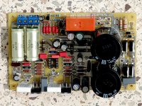
I've received some bare MiniRef boards from Eric and populated it over the weekend - the first tests with a monolithic opamp (NE5532) this morning went fine and the audible sonics are excellent, and the output DC offsets are a nominal 8.9/10 mV. I'll test it a bit further before hooking up the Salas shunt regulators and swapping out opamps for the discretes. Here's a pic of the prototype build, with moderately premium components across the board in the audio signal path, but nothing outrageously expensive.
Attachments
Last edited:
Is your schematic and pcb design open for public?
I wonder if i could join for build this one
Sure, the schematic and the layout of the LM1875-based MiniRef v1.02 have been posted earlier in this thread. Eric's board has some additional improvements, including a separate shunt regulator for the opamp - please contact him directly for his boards. My (successor) boards use LM3886 instead, and work OK but are still being refined for stability.
If you want something that works well, with moderate power (~20W) into 8 ohm loads, go with Eric's LM1875 boards and keep the rails comfortably low (say +/- 24V or lower).
")
Hi Prezden, I guess Mr Erick's ID is PreSapian diyAudio - View Profile: PreSapian
http://www.diyaudio.com/forums/members/presapian.htmlhttp://www.diyaudio.com/forums/swap...tyrene-caps-150-220-1000pf-4.html#post3614272
http://www.diyaudio.com/forums/members/presapian.htmlhttp://www.diyaudio.com/forums/swap...tyrene-caps-150-220-1000pf-4.html#post3614272
Update: I have tested and validated the LF06 (FET990) Class-AB and the LF05 folded-Kaneda Class-A discrete opamps as stable outer-loop opamps in the MiniRef 3886 (in almost all cases, anything that works in the MiniRef 3886 will also work in the MiniRef 1875 - though the converse isn't necessarily true).
At the moment, the best-sounding discrete that I've auditioned in the MiniRef is the FET990, while the best-sounding monolithic is hard to state with certainty - LME49720 and OPA2134 both seem to fit the bill; I'll give AD8022, LM6172 and LT1361 a try later, though they're all pretty fast and potentially unstable.
At the moment, the best-sounding discrete that I've auditioned in the MiniRef is the FET990, while the best-sounding monolithic is hard to state with certainty - LME49720 and OPA2134 both seem to fit the bill; I'll give AD8022, LM6172 and LT1361 a try later, though they're all pretty fast and potentially unstable.
- Home
- Amplifiers
- Chip Amps
- MiniRef Schematic and PCB layout