Hello all,
I want to use Tda7293. I do not want a discrete or LM configurations.
The amplifier will have 3 TDA7293 in paralel for paralel only configuration, or 2 IC paralel conected in bridge with 2 IC paralel (4 IC per channel).
What is the best configuration for best sound? (under these conditions")
Power supply 2*40V, load 8Ohm (150W RMS/250W Music for speakers).
The amplifier will be used 90% from time at 20-30W mean power but I want a very high reserve for peak power (over 150W) and a high slewrate.
I searched the forum but have not found a clear answer.
Thank you
I want to use Tda7293. I do not want a discrete or LM configurations.
The amplifier will have 3 TDA7293 in paralel for paralel only configuration, or 2 IC paralel conected in bridge with 2 IC paralel (4 IC per channel).
What is the best configuration for best sound? (under these conditions
Power supply 2*40V, load 8Ohm (150W RMS/250W Music for speakers).
The amplifier will be used 90% from time at 20-30W mean power but I want a very high reserve for peak power (over 150W) and a high slewrate.
I searched the forum but have not found a clear answer.
Thank you
The sonic differences, if audible at all, will be small enough to be a question of taste. You won't find a clear answer except if you build both and compare them yourself.
From a heatsinking point of view it makes more sense to either use 2 single ended ICs in parallel or 3 BTL in parallel.
If the datasheet specifies that ±40 V give 100 W into 8 Ohm (10 % THD!), it is not likely that you get 150 W just by using several ICs in parallel.
90% at 20-30 W mean power? Either your speakers are really bad or you are deaf or you soon will be.
Just to elaborate on pacificblue's comment: If we guess that your speakers have low efficiency, say 85 dB @ 1 W @ 1 m, we can guesstimate that 30 W is somewhere around 99 dB @ 1 m for one speaker. We can also conveniently guess that the loss in SPL due to the listening distance being greater than 1 m roughly cancels with the gain from using two speakers, leaving us with an average SPL around 99 dB in the listening chair using two channels of 30 W each.
However, uncompressed music has a dynamic range of perhaps 20 dB, so to reproduce real musical dynamics you will need quite a bit more power than the average level. 20 dB peaks takes 100x more peak power than the average. So, if your 20-30 W mean is correct, you should be looking at something that can deliver 2-3 kW peak for correctly scaled musical dynamics (and inventing speakers that can take all that power without melting). 20 dB peaks above 99 dB average will be really loud, as in a jet fighter taking off 200 ft away. Of course, if you only listen to highly compressed pop music, you might not need more than 9-12 dB headroom, or somewhere in the 150-500 W range. All assuming that your 20-30 W average is correct.
I'm curious: What speakers are you going to drive with these, for what type of music, and in what sort of room? How did you estimate 20-30 W mean power?
Last edited:
Ok! Maybe the power is to big but I know what I mean.
My speakers have a high sensibility and are good enough to deafen anyone in normal circumstances when use this power.
Maybe under 20-30W is the correct expresion, but if this power is used in 20-80Hz bandwidth you will see that is not to much.
At ±40 V the peak power is around 144W
(power supply - voltage drop in IC (~6V)) squared /Rload.
In bridge configuration the peak power is around 578W
(positive power supply + negative power supply- voltage drop in IC (~12V)) squared /Rload. In the same time the slewrate will be double.
The peak power is specified only from cliping poit of view.
In bridge configuration the cliping will be at a very high output and is unlikely to be touched.
Question is whether it is worth the complication and the necessity of enlarging the heatsink.
When I will finish I will post the layout together with a complexe protection and maybe some photos, but I need your help until then.
And pacificblue I like you post.
I think that here there are people that allready made these tests.
I do not have enough time to test every configuration and is a good ideea to have a second opinion.
To limit the discution my speaker have 91dB @ 1 W @ 1 m, so more than you consider.
My previous posts provide enough information to generate an image about what I want.
I do not want power and sound pressure calculation. The forum is full with this and I don't know who needs this in real life at home.
Pacificblue what means 3 BTL in parallel? 6 IC's per channel? This was my first idea but I do not have enought space for so many IC's.
This amplifier need to be fit inside of an old amplifier box.
Asbjbo by the way you have been at least once near a military plane taking off when the afterburner lit? I was once and know very well what it means. And to not start another comment I do not have any problems with hearing.
I start this topic to have a second opinion regarding my question not to read a lot of breastbone comments. If this is the only comments that you can do beter not.
This is a very non technical reply to your bridging vs paralleling vs bridged/parallel.
If very good discrete based on lme498xx is given 10/10 for sound quality, then I would rate the three options as:
Single - 9/10
Parallel - 8.5/10 if you feed the same speaker impedance
Parallel - 8/10 if you feed a lower impedance speaker.
Bridged - 8/10 if you feed a doubled impedance speaker
Bridged - 7/10 if you feed the same impedance speaker.
BPA - 8/10 if the speaker impedance is high enough to not trigger any of the protections.
I believe all the multiple chip versions are poorer sound quality than the best single chipamp.
Thank's all of you who reply to my post.
I supose that that these are the only answere that I will receive in this forum.
It was a joke and I hope to receive more reply, maibe from people who made other tests.
Audio electronics is unfortunately not my strong point in electronics but I'll try to give answers, in my time limit on how many posts on that side of electronics were I'm really master.
Firt replay from me in this forum is on Improving heat transfer of IC.
Screenshot's
Hello,
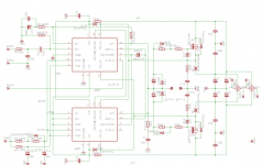
The schematic use two TDA7293 in parallel like in datasheet. I powered the IC's with ±20V on low rail and ±40V on high rail.The G class (power supply modulation) it is applied only to power pins (13 and 15) and it is made with MosFet's.
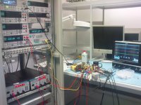
Some measurements and photo of test board and test setup:
Hello,
The schematic use two TDA7293 in parallel like in datasheet. I powered the IC's with ±20V on low rail and ±40V on high rail.The G class (power supply modulation) it is applied only to power pins (13 and 15) and it is made with MosFet's.
Some measurements and photo of test board and test setup:
Attachments
-
 Class G start modulation.png81 KB · Views: 993
 -
 20khz_8ohm_max_power.png92.8 KB · Views: 959
 -
 20khz_square_4ohm_max_power.png87.9 KB · Views: 947
 -
 50khz_4ohm.png94.3 KB · Views: 917
 -
 sweep_10hzto100khz_20khz_marker_.png102.6 KB · Views: 913
 -
 DSC00175.JPG591.4 KB · Views: 504
 -
 DSC00174.JPG616.5 KB · Views: 492
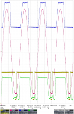
Short explanation is needed.
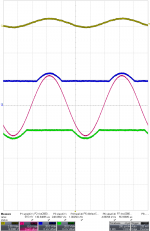
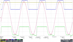
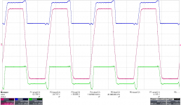
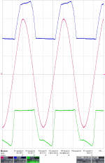
Traces:
blue=G class positiv voltage output=TDA7293 pin13,
green=G class negativ voltage output=TDA7293 pin15,
red=output
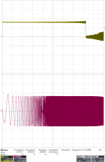
In first screenshot can be seen the basic function of G class. Output 10v/div (~25Vpp, 1KHz), power suplly rail 20V/div, yelow trace=input signal.
In second screenshot: maximum out voltage on 8Ω at the cliping limit, 20KHz input frequency, Yelow trace = cliping signal.
In the third screenshot: 20KHz square signal close to the maximim power.
In the fourth screenshot: 50KHz signal close to the maximim power.
In the last screenshot: frecquecy sweep from 10Hz to 100KHz (logaritmic variation) with marquer at 20KHZ (the tranzition from high to low in Yelow trace correspond with 20KHZ in red trace).
The 3dB bandwidth is 150KHz.
Because the transformators are relatively small, the power high voltage (±) rail are stabilized at ±40V using laboratory power supply. Only with transformators, the power supply drop from ~±45V to ~±35V.
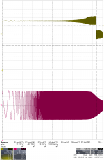
Next screenshots show G class distorsions at 20KHz and maximum power on 4Ω load on zoom screen (20X zoom, ~0.24% distorsions) and respectively cliping signals when cliping it is present on 4Ω load.
Traces:
blue=G class positiv voltage output=TDA7293 pin13,
green=G class negativ voltage output=TDA7293 pin15,
red=output
In first screenshot can be seen the basic function of G class. Output 10v/div (~25Vpp, 1KHz), power suplly rail 20V/div, yelow trace=input signal.
In second screenshot: maximum out voltage on 8Ω at the cliping limit, 20KHz input frequency, Yelow trace = cliping signal.
In the third screenshot: 20KHz square signal close to the maximim power.
In the fourth screenshot: 50KHz signal close to the maximim power.
In the last screenshot: frecquecy sweep from 10Hz to 100KHz (logaritmic variation) with marquer at 20KHZ (the tranzition from high to low in Yelow trace correspond with 20KHZ in red trace).
The 3dB bandwidth is 150KHz.
Because the transformators are relatively small, the power high voltage (±) rail are stabilized at ±40V using laboratory power supply. Only with transformators, the power supply drop from ~±45V to ~±35V.
Next screenshots show G class distorsions at 20KHz and maximum power on 4Ω load on zoom screen (20X zoom, ~0.24% distorsions) and respectively cliping signals when cliping it is present on 4Ω load.
Attachments
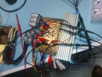
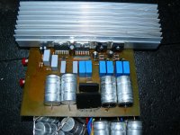
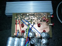
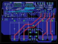
High resolution photo of the test board.
The filtering is 4*2200µF/40V low ESR on every power rail.
During the test with sinusoidal signal, the heat spreader become relativly hot (around 60-70°C).
During the listening at high room level, the heat spreader remain at room temperature, I mean that I can't see any temperature change of it.
This is normal because is not any sense to use G class for sinusoidal signal at maximum power.
The class G advantage is maximum when it is used with music signal with a high crest factor.
If there are people interested in this project I can provide more details.
The test board start from first power on, and I do not experienced any problem like other people that worked with this IC.
It remain stable down to 2Ω on resistive load during the testing.
Finally I want to use ± 50V on high rail and ±20V on low rail to obtain around 100W on 8Ω.
Attachments
measurements details
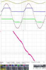
Photo with bandwidth measurement: frequency sweep from 10Hz to 300KHz (logarithmic variation) with marker when the level decrease to 0.7 (23.1V at 150Khz and 32.73V at low frequency) at 150KHZ.
The slew-rate it is around 8.4V/µs, in limits of datasheet.
The stability is ok without zobel on output for frequency from 10 hz to 20Khz, sinus, 90% from max power on 8Ω and 70% from max power for 4Ω.
With zobel all instability was solved. Stable until 2Ω max power (cliping limit) from 10 hz to around 150Khz and square signal of 20Khz.
Attachments
Hi flaotte,
I can't to post today, maybe tomorow but I think the resolution it is enought because the component values are not updated. The values of components are only to have an idea and are not the test used components.
The values of components that I will finally use will be optimised for the final layout, thaking in consideration that this was a test board.
The final layout it is a big board (~200x300mm) with 2 channells, complex protection circuit, fan controll, power supply's, basic preu and connections for future extension boards. The equalyser (2x5 band's) are allready made and tested on diferent board. The pcb layout are allready made.
Unfortunately now the project it is in standby for a long period because I do not have enough time to finish it.
Ok, in that case no need for bigger res image. I would like to make this amp for sub-woofer.
G class for LFE movie woofer looks perfect.
are you going to publish final amplifier?
It will be my first amp. I have some experience, but most of it are digital circuits.
Are there any suggestions?
What kind of transformer do I need for two parallel chips? 200VAC for mono?
G class for LFE movie woofer looks perfect.
are you going to publish final amplifier?
It will be my first amp. I have some experience, but most of it are digital circuits.
Are there any suggestions?
What kind of transformer do I need for two parallel chips? 200VAC for mono?
Hi,
If will be people interested yes, but I do not know when I will have time to finish.
When I start this project I was interested to finish it to be used at my home for listening. Now I have a verry good comercial amplifier for this task and the finish date was postponed for a undefined time.
Regarding of transformer depends of many things. Type of music that you listen, the average level of power, the impedance of driver....
The ±50t is the maximum for TDA7293 and at this volatge on high rail the output RMS power it is over 120W/8Ω and 200W/4Ω (depends of traf and capacitors). For 4Ω at ±50V two paralel IC are not enought because of current limitations. People from this forum consider that it is neccesar a peak current capability of at least 3 time more than RMS current.
For me a 200W transformer it is enought for mono aplication, for other people you will need over 300W.
In any case the capacitors are verry important now and you will need minimum 10-20mF per rail. The advantage is that you can use a low voltage capacitors (35V) and to connect it in series with midle point at low rails voltage (there are 4 rail power supply).
The diodes between pin7 and pin13, and between pin8 and pin15 are verry inportant to be Schottky (1A it is enought). C1 and C2 filter the voltage for input and VAS sections. I used only 10U low ESR and was suficient.
I look forward to hear how it works yours amplifier!
- Status
- This old topic is closed. If you want to reopen this topic, contact a moderator using the "Report Post" button.
- Home
- Amplifiers
- Chip Amps
- 7293 parrallel or bridge/paralel for best sound?