Hey guys!
Ive got a crappy home theatre sub hooked up to an LM3886 amp that I built awhile ago, and its still pounding along great! However, Im looking into upgrading, and thus I need advice.
Ive settled on 2 10" Alpine Type-R's. They have dual 2-ohm voice coils and are rated at 500w RMS. This means I can have the following impedance configurations:
- two 1 ohm loads
+ one 0.5 ohm load
+ one 2 ohm load
- two 4 ohm loads
+ one 2 ohm load
+ one 8 ohm load
One issue thats popped into my mind this far is how I am going to drive the subs. Will I have one big amp and hook them both together? Or should I drive them separately? Common sense tells me that if I drive them separately, they need to be in separate chambers, whereas if I drive them as one I can have them both in the same chamber. Ideally this is what I would like to do.
Now, I know Im not going to build a 1kW amp to power these subs - I have no intention of doing that. I was hoping for around ~200-300w per sub. Seems reasonable?
Ive looked into the following:
- bridged/parallel'd LM3886's - I would need quite a few of them
- parallel'd TDA7293's - 2 would give me ~250w into 2 ohms, are they 0.5-ohm stable?
- a more complex driver, the LME49810/30 - I have no experience with this chip at all
What do you guys recommend? Any and all ideas are welcome!
Last edited:
cheapest solution that will probably be loud enough:
set up each speaker to 4 ohms.
get one 220va 22 0 22v( 18 0 18 should be safer) toroidal , a nice large heatsink and around 22000uf per voltage rail. and use one lm3886 per speaker. (2 lm3886 in total)
More expensive solutions that will give more headroom:
Set up each speaker as 4 ohms.
Get one 400va 25 0 25 transformer and at the very least 22000uf per voltage rail and use 2 x lm3886 in parallel per speaker. (4 in total)
lm3886's in parallel is tricky. You need to get expensive 0.1% resistors.
good luck
I agree with Tang:
set up each driver as a 4ohm with the two 2ohm voice coils in series.
Choose an amplifier that will run from a 40Vac+40Vac or 45Vac+45Vac or 50Vac+50Vac transformer.
The lme498xx driver chips come in 3 versions. Download the 3 datasheets and compare what each is better at doing.
This is the easiest way, by far, to get 200W to 500W into a speaker.
From my research:
LME49811 - little bit more output current, output devices are bjt's
LME49810 - built in baker clamp (why would I want this?), output devices are bjt's
LME49830 - output devices are fets
What would be better for my situation, fets or bjt's? Which parts would you guys recommend? I have no idea where to begin with output drivers. However ON Semi has a pretty good sample program so Ill likely order my drivers from there, whatever they may be. Im quite familiar with Eagle so Ill be designing my own PCBs aswell.
Hi,
look at ONsemi MJ21193/4 and MJL21193/4
The To3 versions are reputed to be very rugged.
For drivers MJE15034/5, only 4A but massive SOA for a To220
For a bass amp I'd go for the 810 using BJTs.
For a really good wideband amp I'd use the 811 with an output triple, (the pre-drivers are already in the 810).
Now go and find all the threads on the LME series and read read read.
Come back with questions in the appropriate threads.
Hey guys, Im back!
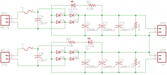
After lots of reading Ive settled on a design, and Ive gotten started on it. Ive attached to this post 3 images:
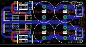
- PSU schematic
- PSU board design
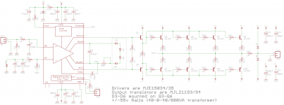
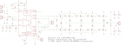
- Amp schematic
The design is based off Panson Audio's driver & power boards. Im holding off on doing the board layout for the amp until people more knowledgeable than me can have a look at it.
My load will be either 0.5/2/8 ohms, depending on the voice coil configuration. Which one is the most efficient? I would assume the smallest load resistance, but Im sure there are practical problems that get in the way. Im sure this obvious, but how do I calculate the approximate output power of the amp?
Also, this is the transformer Im using.
The boards will be etched by me (the first run anyways), hence the lack of silk on the PSU board. If Ive forgotten anything, please let me know!
After lots of reading Ive settled on a design, and Ive gotten started on it. Ive attached to this post 3 images:
- PSU schematic
- PSU board design
- Amp schematic
The design is based off Panson Audio's driver & power boards. Im holding off on doing the board layout for the amp until people more knowledgeable than me can have a look at it.
My load will be either 0.5/2/8 ohms, depending on the voice coil configuration. Which one is the most efficient? I would assume the smallest load resistance, but Im sure there are practical problems that get in the way. Im sure this obvious, but how do I calculate the approximate output power of the amp?
Also, this is the transformer Im using.
The boards will be etched by me (the first run anyways), hence the lack of silk on the PSU board. If Ive forgotten anything, please let me know!
Attachments
Last edited:
Nice but one thing: get rid of those 'boutique' TO-220 diodes and use bridge rectifiers like this: Digi-Key - GBJ2506-FDI-ND (Manufacturer - GBJ2506-F)
For next time I will - I have 10 mur860's from a previous sample order to use up. May as well use them!
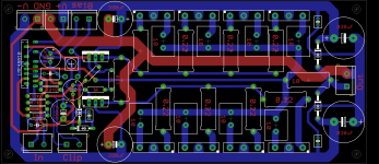
On the positive side, I was bored after uploading and decided to do up a board for the amp. It's attached to this post. Again, comments are welcome, Im by no means a "professional" at this stuff (just an EE student who's always after cleaner fuller bass). Ive slightly modified the schematic so Ive reattached it aswell.
On the positive side, I was bored after uploading and decided to do up a board for the amp. It's attached to this post. Again, comments are welcome, Im by no means a "professional" at this stuff (just an EE student who's always after cleaner fuller bass). Ive slightly modified the schematic so Ive reattached it aswell.
Attachments
Last edited:
A 40-0-40 transformer using a 4pr output stage cannot drive half an ohm of reactive speaker.
It might just be able to drive a 2ohm reactive speaker but you would have to ensure it can never run hot. Cool to warm will require big heatsinks.
8ohm ohms speaker will pull a maximum output power of between 160W and 180W per speaker.
4ohms or parallel 8//8ohm would seem ideal for your amp proposal.
No output Zobel.
DC coupled.
NFB at opposite end from speaker feed.
Last edited:
For next time I will - I have 10 mur860's from a previous sample order to use up. May as well use them!
Hi,
My caution was for durability. The bridge rectifier has MUCH higher current capacity and you have a hefty transformer. Diode failure is the last thing you'd want.
The board layout isn't too bad but look at the base resistors and emitter resistors on the outputs - there is a mistake.
Last edited:
You are correct! I knew I was missing something. In the original design the inductor is shown as 10 turns around the 10 ohm resistor - I didnt want to have an extra footprint next to the resistor for the inductor, so I plan to solder the wire onto the resistor itself - hence, the inductor will still be there, it's just not in the diagramThat 10 ohm resistor is going to be dissipating over twice the energy you are putting into your speakers. It will smoke instantly.
Methinks your are missing an inductor.
") Sorry for the confusion.
Sorry for the confusion.Something else I forgot to mention, the output Zobel will be mounted directly on the binding posts for the speaker, so it's not included in the design either.4ohms or parallel 8//8ohm would seem ideal for your amp proposal.
No output Zobel.
DC coupled.
NFB at opposite end from speaker feed.
Where would be a better place to take my NFB trace? As for the impedence, if 4 ohms is best for me, I will switch to 2x dual 4-ohm subs, for a final impedence of 4 ohms.
Fair enough - I certainly dont want my diodes to fail, so I will redesign my power supply using similar bridges to the one you linked.Hi,
My caution was for durability. The bridge rectifier has MUCH higher current capacity and you have a hefty transformer. Diode failure is the last thing you'd want.
The board layout isn't too bad but look at the base resistors and emitter resistors on the outputs - there is a mistake.
As for the mistake, Im sure you know how it goes - Ive been staring at my design for awhile and I dont see the mistake, but if it were someone elses design Im sure it would jump right out at me. Care to be a gent and point it out to me?
A Zobel after the L//R is partially isolated from the output stage.the output Zobel will be mounted directly on the binding posts for the speaker, so it's not included in the design either.
It cannot work in the same manner as a Zobel across the output stage.
If the "amplifier" is designed to operate into a variety of loads then the Zobel is part of the amplifier.
A Zobel across the output terminals is very effective at attenuating RF picked up by the speaker cables and providing a load when the speakers are disconnected. If located at the Speaker binding posts then it cannot load the amplifier when the speakers are disconnected and if located at the far end of the speaker cables cannot provide effective attenuation of RF picked up by the cables.
Care to be a gent and point it out to me?
No problem. You have the 10 ohm base resistors on the emitters and the .22 emitter resistors on the bases.
Also, the 10 ohm base resistors do not have to be high wattage - 1/4 or 1/2 watt would be fine.
Last edited:
Are you sure it's backwards? This (attached image) is how Im picturing it in my head, and Ive double-checked the datasheet.No problem. You have the 10 ohm base resistors on the emiiters and the .22 emitter resistors on the bases.
Also, the 10 ohm base resistors do not have to be high wattage - 1/4 or 1/2 watt would be fine.
Also, youre right, Im not sure why Ive picked 2w resistors for the bases - I will correct that when I get home from class.
Attachments
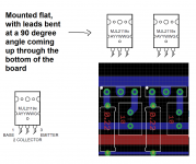
Are you sure it's backwards?
Certainly appears to be, unless you are mounting the outputs face down.
Remember, all board layout views are from the top.
- Status
- This old topic is closed. If you want to reopen this topic, contact a moderator using the "Report Post" button.
- Home
- Amplifiers
- Chip Amps
- Subwoofer Amp Design Suggestions