Hi all.
I am in the process of building my first gainclone, using chipamp.com's LM3886 stereo kit. I would like to have a headphone jack in addition to speaker outs. Any advice on how to do that?
I would love to avoid adding another switch/knob to the front of the chassis. I'm picturing power switch on the left, volume knob and LED in the middle, and a headphone jack on the right.
If it matters, my current headphones are Grado SR80, and Shure SRH440.
Thanks in advance for any advice,
Josh
headphone jack has three terminals...gnd, right hot, and left hot...
connect amp gnd to jack gnd.
amp right==>100 Ohm 1 Watt==> right hot
amp left==> 100 Ohm 1 Watt ==> left hot
This leaves the speaker outputs live all the time...as well as the headphones...
There is a way to connect them like commercial units
when you plug in headpone the speaker is disengaged. I think the
ground connection is common to both so either one is on or off.I'm not too
sure but only plug in/out headphone when power is off or else may damage speak or amp and volume at zero.Hope this helps.
edit: I think 100 ohm alone is too dangerous better use a voltage divider to make sure heaphone
amp only gets a certain amount of signal voltage to not over drive it.There is a way to calculate
a voltage divider just do a search.That is the tap to headphone is between the 2 resistors and
the other end to ground if that makes any sense to you,that's the proper way I think.
Still the safest way is the switch method.This is a high power amp.
Regards.
Last edited:
Thanks all. I'm intrigued by the jack/switch combo you suggested. Since I have a baby in the house, I'd like to plug in phones and have the speakers switch off. I cannot tell from the diagram of the part how I would go about hooking it up. Sorry to be ignorant, but I'm new at this... Can you help with what wires go to which terminal? Do you still think 100 Ohm 1 Watt resistors for the phone jack is the ticket?
Josh
Josh
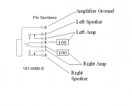
Here's the wiring
I'm guessing a bit about left versus right....the supplied pinout with the earlier pdf was kind of vague.
Still, you won't go wrong if you remember that Right is Ring and Left is Tip, at least according to my Grado Headphones.
With no headphones plugged in, 2 and 3 are connected.
With no headphones plugged in, 7 and 6 are connected.
So, with no headphones, the right amp connects to right speaker, and the left amp connects to the left speaker.
Connecting the headphones pushes apart 2 and 3, and pushes apart 6&7, disconnecting the speaks from the amps.
Note also with this arrangement, the headphones are always energized, even though the speakers get cut on and off.
Hope this helps.
Attachments
starting here...too many options...panel mount, pc, right angle...etc.
you'll have to narrow it down...
Phono (RCA) Connectors
you'll have to narrow it down...
Phono (RCA) Connectors
if you want speaker turn off when TRS plug is inserted you will have to re-route the speaker wiring through the TRS socket first and then to the speaker output terminals.Can you recommend good RCA inputs and banana jacks for my project?
When you do this, all the other connections become irrelevant to sound quality options.
I agree with Singa.
We both advise that you create a voltage divider. You need the two 100r as already suggested and two 10r.
Wire the 100r as said in series from speaker to TRS socket.
wire the 10r from Headphone Hot to Headphone Ground on the back of the socket.
I'm still thinking how the TRS socket allows speaker switching and resistor ladder for headphone attenuation.
A normal TRS socket has 6 connections, one pair on each of T, R & S, not as shown in post7
Last edited:
most commentators that claim some or a lot of sound quality improvement from the types of hardware used would never agree that replacing the direct route from amp to speaker terminal with amp to TRS socket, across the TRS socket contacts and then TRS socket to speaker terminals will provide potential for improved sound quality.
I will go further, if sound quality is important do not re-route the speaker cables via the TRS socket.
I will go further, if sound quality is important do not re-route the speaker cables via the TRS socket.
The contacts in most jacks really aren't designed to handle much current.
I know you don't want to add another knob to the front panel, but sometimes you can remove the speaker selector/HP switch assembly from a junked receiver for this purpose. Look for something with hefty switch contacts.
Or just buy a switch.
John
I know you don't want to add another knob to the front panel, but sometimes you can remove the speaker selector/HP switch assembly from a junked receiver for this purpose. Look for something with hefty switch contacts.
Or just buy a switch.
John
OK, here's my next idea. Can I just connect another pair of RCA jacks in parallel to the input RCA jacks and use them as an output to a headphone amp? I don't think I would have to power the chip amp up to get the signal through the RCA jacks to the headphone amp. In this scenario, would the connection to the headphone amp change the input current to the chip amp if the headhpone amp were off? What if they were both on? Thanks for your thoughts...
Using a Y-cable would be electrically equivalent to this - either would work just fine, I think.OK, here's my next idea. Can I just connect another pair of RCA jacks in parallel to the input RCA jacks and use them as an output to a headphone amp? I don't think I would have to power the chip amp up to get the signal through the RCA jacks to the headphone amp. In this scenario, would the connection to the headphone amp change the input current to the chip amp if the headhpone amp were off? What if they were both on? Thanks for your thoughts...
Or you could buy a switch box for a few dollars, or make one, or put a switch in to control the routing through the RCA jacks you install - IN/Bypass sorta thing....
Lots of possibilities....
- Status
- This old topic is closed. If you want to reopen this topic, contact a moderator using the "Report Post" button.
- Home
- Amplifiers
- Chip Amps
- Help with headphone jack