Hello, I'm new here
from my friend i got some schematic of power amplifier using KTB688+KTD718 transistor rated 45-50W. However before this i found a hobby kits of audio amplifier using STK4141 II rated 100W...
The question are :
Which is better in term of audio quality ( normal usage; Computer sound system)?
Which are durable and long lasting (over heating, short circuit)?
Best of overall, which amplifier type preferred ?
Thanks,
[comment]However before this i found a hobby kits of audio amplifier using STK4141 II rated 100W...
[/comment]
As far as I have known STK 4141 can deliver upto 70W/ch at a very high distortion rate and with heavy heat sink. I hope the hobby kit does not quote 100W/ch!
hahaha... from the hobby kit it state "100W+100W"
from datasheet STK 4141
STK4141 X = Rated 75W
STK4141 V = Rated 25W
I'm sure about this info,
but i want to know the nowdays trend, most hifi, audio system and a home theatre today, they are using still using STK or Just a pair of transistor for each channel ?? any one here has the info??
STK4141 X = Rated 75W
STK4141 V = Rated 25W
Sorry, but even STK4141 X is rated at 25W/ch, I think one gets confused by looking at the Data sheet for STK4141 X "series" datasheet where they mention about all the chips in that series like STK4141X, STK4151X...STK4191 then STK4201X, STK4211X in a single data sheet.
STK4211X is rated at 70W/ch.
STK4141 X can deliver 70 W/ch at a very high distortion rate but would need a heavy heat sink and supply upto the max rated supply inputs.
I am aware STK chips were used by Sony, Akai, Panasonic, Aiwa etc for their component systems heavily several years ago, but I am myself interested to know what they are using these days in component systems

but i want to know the nowdays trend, most hifi, audio system and a home theatre today, they are using still using STK or Just a pair of transistor for each channel ?? any one here has the info??
Your post forced me to do a lot of research on sony audio equipment especially as my own interest was also involved here
. Here are some of the results.For its famous Hi-Fi component systems (MHC series) Sony still uses STK series chips like STK411-XXX, STK433-XXX.
For seperates/Home Theater systems it uses transistor based power amps usually driven by a IC based driver for eg MN2488+MP1620 driven by UPC2581 etc..
I hope this give you some insight into what is being used these days by Sony etc
IndAudio, Thanks for the info.
actually this information is for my project. the project using recycled hi-fi casing.(all contents removed). there, i will integrate iPod Docking, FM radio, and USB mp3 modulator(some mod) and AUX input. after that the system goes to pre amplifier(bass/tre/vol) by National Semi- LM1036N and now i'm choosing the suitable power amplifier either using transistor or STK which is simple choice that available easily by hobby kits..
actually this information is for my project. the project using recycled hi-fi casing.(all contents removed). there, i will integrate iPod Docking, FM radio, and USB mp3 modulator(some mod) and AUX input. after that the system goes to pre amplifier(bass/tre/vol) by National Semi- LM1036N and now i'm choosing the suitable power amplifier either using transistor or STK which is simple choice that available easily by hobby kits..
All the best for your project, publish a few pics once you complete it.
You could use STK4141 kit if it is readily available. But here are a few words of caution :
1. Make sure you are getting genuine and not a fake STK (google for STK fakes and you will know how to make out the difference).
2. The PCB should be of good quality with proper layout, often people blame STK for failures on the PCB side. I am not an expert on PCB's so not much I can say apart from this.
3. Go through the data-sheet for STK4141 (make sure you get the datasheet for appropriate mark like II, V, X).
However if you want to use the KTB688+KTD718 transistor's then others need to advice you. I have worked with transistors only once, though I liked the sound quality very much (I used 2955+3055 pair), I dropped the idea of using any other for space and heat-sinking requirements, I think my circuit was poorly designed and hence dissipated a lot of heat!!
Muid
IndAudio, Thanks for the info.
now i'm choosing the suitable power amplifier either using transistor or STK which is simple choice that available easily by hobby kits..
You could use STK4141 kit if it is readily available. But here are a few words of caution :
1. Make sure you are getting genuine and not a fake STK (google for STK fakes and you will know how to make out the difference).
2. The PCB should be of good quality with proper layout, often people blame STK for failures on the PCB side. I am not an expert on PCB's so not much I can say apart from this.
3. Go through the data-sheet for STK4141 (make sure you get the datasheet for appropriate mark like II, V, X).
However if you want to use the KTB688+KTD718 transistor's then others need to advice you. I have worked with transistors only once, though I liked the sound quality very much (I used 2955+3055 pair), I dropped the idea of using any other for space and heat-sinking requirements, I think my circuit was poorly designed and hence dissipated a lot of heat!!
Muid
Last edited:
When mass manufacturers decide on an amplifier technology they usually start by defining the specifications the amplifier has to comply with. Then they check how to meet those requirements in the most economical way. At low output power the chip amp (like LM3886 or TDA7293) or hybrid amp (like the STK series) is usually the choice. The higher the output power the more likely is it that a discrete amplifier costs less money to develop and build.
We are now starting to see a transition to class D (often wrongly called digital), because that technlogy becomes easier to master all the time and its space, heatsinking and power supply requirement advantages tend to outweigh the additional engineering effort.
Whether a chip or hybrid amp sounds better than a transistor amp depends on how good a design you use. A chip or hybrid amp is easier to get right. For a computer sound system it is the more logical choice. If you look e. g. inside of Logitech products, you will always find chip amps doing the job.
I dropped the idea of using any other for space and heat-sinking requirements, I think my circuit was poorly designed and hence dissipated a lot of heat!!
Or maybe it was not poorly designed but class A. The heat dissipation for a given output power is the same and from a certain power upward the lower thermal resistance of several transistors compared to a chip amp rather leads to smaller heatsinks.
If same "additional engineering effort" were given to class B then efficiencies could be very similar.We are now starting to see a transition to class D (often wrongly called digital), because that technlogy becomes easier to master all the time and its space, heatsinking and power supply requirement advantages tend to outweigh the additional engineering effort.
If same "additional engineering effort" were given to class B then efficiencies could be very similar.
We call that class G or class H where the power supply voltage is adjusted to the load situation to reduce losses. You can indeed achieve similar average efficiencies to class D.
We call that class G or class H where the power supply voltage is adjusted to the load situation to reduce losses. You can indeed achieve similar average efficiencies to class D.
Well, I have the opinion that ordinary class AB or class B will come very close to class D efficiency, if the design is super-stable, run on clean power, and. . . if the class AB or class B amplifier has an additional circuit to cut the load on idle (like a screen saver sort of function).
When class AB or class B is both designed well and busy doing work (without doing extraneous non-audio work), then its actually very efficient.
The biggest caveat on comparison is that its very rare for class AB or class B to be designed with power saving efficiency in mind.
The second biggest caveat on comparison, is that the significance of Class D's efficiency is often exaggerated because its "New! and Improved!," such as "look mom! no heatsink!" and this is pretty stupid because the heatsink requirement of Class D is identical to Class B when both are compared running full blast, doing the same work. Its most frequently reported in prosound when the Class D has undersized heatsinks as a sort of efficiency brag, emits smoke (awful smelling olive color smoke) and fails.
Also reported is less impact, such as less current. Doing less work is absolutely not the same as greater efficiency, but the concept is similar enough to mislead the unwary.
Unfortunately, examples of hyper-efficient linear are rare, but I'm just saying that:
They're not impossible
They'd be commonplace if they were designed with energy efficiency in mind.
Here's a little start:
Attachments
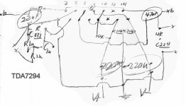
The datasheet design of that TDA7294 amp is super hot running.
That which is posted above is Cold running, but needs a few touch ups.
The mute can stay tied to that 10k, but the standby needs a detector timer (screen saver function) to konk the amp when its not doing work. This is the majority of the efficiency difference between class D and class AB.
The 220uF need a single 2uF Polyester added at rail to rail.
They also need small value polyster, such as 100nF (or less!) bypass caps.
The NFB cap needs some caphackery to increase the bandwidth to within the range that the inverting input resistor may be 2k~3.3k. Add 0.0047uF ceramic or polypro to the 22uF. Add a 3.3R 1/2w carbon to the groundside pin of the 22uF. Add a 220uF//0.47uF to the hotside pin of the 22uF, to create this thing:
22uF//0.0047uF//((220uF//0.47uF)+3.3R) or in other words, the larger cap (and its bypass cap) has series resistance added so that it is less likely to play except during its own bandwidth.
Feedback resistor is in the neighborhood of 120k
Its partner is in the range of 2.2k~3.3k and the example actually used 2.7k.
RF filters need to be added or more clearly stated in the design.
The typical op-amp stabilizer capacitor may be added between inverting and non-inverting input.
Types of caps used:
Surprisingly, all 3 of the 220uF need to be signal grade, such as the Panasonic that everyone talks about or the Chinsan Elite PS which is similar.
The 2uF polyester rail to rail cap is a cheap tweeter cap and needs to be the sort that you wouldn't use as an input cap.
The 22uF is a Nichicon KZ although a Cerafine or an ordinary power cap would do fine. The 0.47uF is a Nichicon ES, but any signal grade cap will do. The input filter cap is "classic combo" which could be Nichicon ES + a small polyester or Cerafine + a small polyester.
Caveat (same as STK): The TDA7294 can run cool and can do hi-fi but it can't do that on junk. This is exactly the same caveat as the STK chips and mostly about the same sound. Both require a great deal of attention to the power supply. Like the STK, one would be unable to level the frequency response and simultaneously provide clarity and coolness unless the power is high quality.
Like with the STK, while you could tinker with a linear power supply and eventually get everything balanced, the fast trip to hi-fi is with a capacitive multiplier.
The only magic in the chip is the different presentation provided by a FET in my example here and we did put a lot of gain on it in this example (in case of computer or mp3 player or tv). And, like most STK, the TDA7294 has the majority of the work in the power circuit.
Given the great deal of fine tuning of the power circuit, the example doesn't require any larger heatsink than would be required for a class D amplifier. However, I'd like to suggest that you double this in case of 4 ohm speakers might happen to be attached someday.
Yes the design indicated (because it runs cool with 8 ohm speakers) has the tolerances run 4 ohm speakers from a single chip, and it has physically passed long term testing while actually operating 4 ohm speakers.
That, because of the firmer load nonstop, does reduce the energy efficiency, except that doing more work is not exactly the same thing as decreased efficiency. However, parallel amplifier and/or variable hybrid current drive add-on is recommendable for running cooler with 4 ohm speakers.
Although the design doesn't output significant DC offset with the NFB cap absent, if you disconnect the NFB cap, you also disconnect your dynamics. So, please DO leave the NFB cap in place and do a good job with it.
If using parallel amplifier, you can parallel more 220uF power caps (and little polyester box bypass caps) if you want to, but use only a single 2uF "rail to rail" cap at the power input of the amplifier board. Other areas with capacitors aren't duplicate on parallel amplifiers.
This amplifier, if parallel, can be bridged and still yet run 4 ohm speakers, to about 250 watts per channel. Dual mono (looks like monobloc within one enclosure) power is recommended in the case of parallel+bridged. Triple parallel is recommendable, but not strictly necessary.
If you'd rather have a tube amplifier, this is easily done in just a few steps.
Drive like a tube amp:
Adapt the power amp to variable hybrid current drive per the Rod Elliot and Lenard Audio examples. This "drives like a tube amp" but doesn't sound like a triode.
Next step, the sound of a triode:
Decrease the power amp gain. Purchase a Moosefet.
Create an additional power board with the 2-diode center tap specific rectifier from the wikipedia. Put an 8nf high voltage rated polyester cap across the AC side of the rectifier to avoid transmitting noise. Use 4 of 2200nF caps in an economy split rail supply, even though Moosefet doesn't use split rail. Omit the largest cap and the rectifier from the Moosefet board. Put the V+ and V- from your new power board (just described) into the spot where Moosefet indicates its largest power cap.
This new power board that you just made, attaches to the same center tap transformer that runs the TDA7294.
But, of course you could run 2 separate transformers if you like or you could choose a 25+25+12 toroid, with the handy extra tap.
Omit the output caps from the Moosefet board because the input caps of your TDA7294 will do that job.
Lightspeed attenuator can go in-between the TDA7294's input caps and the TDA7294 chip.
And, there you have every bit of a tube amp, without any tubes. Its your option, if you like.
Your STK chip can do a very similar job to the TDA7294. STK is not a FET amplifier, so the sound is somewhat different. Nevertheless, with equal amount of care (especially good power), it can sound just as nice. In case you missed it, STK chips (and many other options) are gorgeous when run from capacitive multiplier power. There's no magic in the chip. You add that yourself.
Last edited:
The theoretical efficiency of a class B amplifier is 78,5 %. Class D amplifiers usually pass the 90 % mark easily in practice.
You are right that class B amplifiers usually do not reach their theoretically possible efficiency of 78,5 %, but rather 35-60 %. One reason is that they need driver stages which add to the consumption.
What is often overlooked in the comparison is the fact that the efficiency is given at maximum power, while amplifiers are usually rather used at low powers. If you look at the power range where listening usually takes place, you will find that the efficiencies are not that different there.
The big advantage of class D becomes apparent when you take into account that you need to design an amplifier for its maximum output power. That means you can save a lot on the portion of power supply and heatsink that you really only need very rarely, because that is where class D has the higher efficiency.
For your 50~100 watts specification, the TDA7294 provides 60~123 watts. Its durable and has a modicum of protection for durability.
You can choose either Capacitive Multiplier power or plain old linear.
For plain linear power board, you can use an economy form (colloquially: "ladderback") with 8 of economy grade 2200uF 50v caps, 2 of 100nF economy polyester dip caps and 1 of 15a~25a pre-built rectifier. A minimum transformer is 3a, 24, 0, 24 center tap, also known as a 48vct, and a maximum transformer is a 6a 28, 0, 28, also known as a 56vct, which can be found for free in discarded electronics of the past.
You could also choose 4a, 25+25 dual secondaries toroid and wire it either for center tap -or- use 2 of 10a rated 1-piece rectifiers to make a dual secondaries type power supply.
You can upgrade your power supply with a PI filter and an additional pair of sturdy caps. This is a simple prospect, but its not required unless you add the current drive adaptation. The hybrid current drive amplifier uses a larger value for the PI filter's resistors (and the output resistors of parallel amplifiers too) as part of its voicing, to slightly alter the sound of any overdrive.
To enhance durability, I'd suggest to add Radio Production Environment, RF/HF filters. These are a zobel looking form added to input, to output and also a tiny value cap added between the inverting and non-inverting pins of the chip. You never know when a neighbor is going to open key a transmitter or when a defective bit of electronics in your house or any house served by the same transformer might release some noise. Therefore, the design that I gave you has an overlarge blast of airy treble that will benefit from adding the RF filters. You'll want them. And, they're good. If any filtering disturbs your audio, simply change your filter size.
Speakers: This amplifier will overcome 6" woofers unless they're in a sealed box, so 8" and larger is recommended. If you want 6" and smaller woofers, go with an LM1875 amplifier (and lower voltage) instead. If you go with full range drivers, add the variable hybrid current drive adaptation to your amplifier so that you can enjoy a level frequency response.
Consider LM1875:
Back on the topic of computer speakers and 6" or smaller woofers, the LM1875 amplifier would differ in that its going to use 330uF or 470uF caps on its amplifier board, and LM1875 is going to use lower voltage.
LM1875 is so simple that it doesn't even need a "board" since speaker zobel can go on speaker jack and input filter cap can go onto the potentiometer.
Caveat: For longevity, LM1875 absolutely requires parallel if running 4 ohm speakers; however, its still extremely easy and inexpensive.
And, LM1875 would use an 18,0,18 (aka 36vct) transformer with about 4 ampers capacity. The Allied Electronics store brand EI core will do a lovely job. Its center tap is sturdy enough to absorb the return force of your speakers, greatly reducing "ground bounce" so that your amplifier can have a nice deep voice (especially noticeable on parallel amplifier).
The LM1875 as indicated, will make about 27 watts to an 8 ohm speaker or, optionally, a paralleled LM1875 will make more than 50 watts to a 4 ohm speaker. The 27 watts doesn't greatly exceed the mechanical limits of a 6" (8 ohm) woofer. Or, use the Paralleled LM1875 to drive an MTM speaker with a pair of 6" woofers per speaker cabinet and enjoy a significant impact.
LM1875 is "the fast trip to hi-fi" and its output power is competitive with the STK model listed. But, LM1875 is considerably easier to wire, AND its clearer.
Silicone or Mica or Kapton insulators and "Shoulder Washers" are necessary electronic insulation for the amplifiers listed in this thread.
It would be irresponsible to fail to mention that most amplifier designers would prefer that you use either discrete regulated or the simpler Capacitive Multiplier power. I'm just saying that those are upgrades, and it is your option.
Reference:
Production examples of the past, when using STK chips, sometimes employed Capacitive Multiplier power and those are lovely sounding amplifiers--because "clearer power" makes "clearer amplifier," which was considerably and necessarily helpful to the STK product.
For energy efficiency on a computer amplifier, simply purchase a "Smart Stick" auto switching power strip. The computer plugs into the "master" outlet and then the power amp, printer, and monitor plugs into the switched outlets. Whenever the computer sleeps or is shut off, the power amp is likewise shut off.
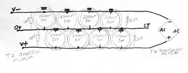
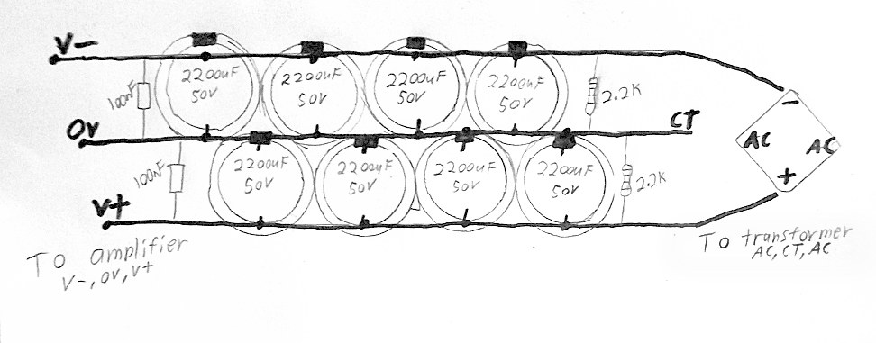
Photo is a simple linear power supply, useful with LM1875 and TDA7294. See how simple? This is especially easy along with some LM1875's
You can choose either Capacitive Multiplier power or plain old linear.
For plain linear power board, you can use an economy form (colloquially: "ladderback") with 8 of economy grade 2200uF 50v caps, 2 of 100nF economy polyester dip caps and 1 of 15a~25a pre-built rectifier. A minimum transformer is 3a, 24, 0, 24 center tap, also known as a 48vct, and a maximum transformer is a 6a 28, 0, 28, also known as a 56vct, which can be found for free in discarded electronics of the past.
You could also choose 4a, 25+25 dual secondaries toroid and wire it either for center tap -or- use 2 of 10a rated 1-piece rectifiers to make a dual secondaries type power supply.
You can upgrade your power supply with a PI filter and an additional pair of sturdy caps. This is a simple prospect, but its not required unless you add the current drive adaptation. The hybrid current drive amplifier uses a larger value for the PI filter's resistors (and the output resistors of parallel amplifiers too) as part of its voicing, to slightly alter the sound of any overdrive.
To enhance durability, I'd suggest to add Radio Production Environment, RF/HF filters. These are a zobel looking form added to input, to output and also a tiny value cap added between the inverting and non-inverting pins of the chip. You never know when a neighbor is going to open key a transmitter or when a defective bit of electronics in your house or any house served by the same transformer might release some noise. Therefore, the design that I gave you has an overlarge blast of airy treble that will benefit from adding the RF filters. You'll want them. And, they're good. If any filtering disturbs your audio, simply change your filter size.
Speakers: This amplifier will overcome 6" woofers unless they're in a sealed box, so 8" and larger is recommended. If you want 6" and smaller woofers, go with an LM1875 amplifier (and lower voltage) instead. If you go with full range drivers, add the variable hybrid current drive adaptation to your amplifier so that you can enjoy a level frequency response.
Consider LM1875:
Back on the topic of computer speakers and 6" or smaller woofers, the LM1875 amplifier would differ in that its going to use 330uF or 470uF caps on its amplifier board, and LM1875 is going to use lower voltage.
LM1875 is so simple that it doesn't even need a "board" since speaker zobel can go on speaker jack and input filter cap can go onto the potentiometer.
Caveat: For longevity, LM1875 absolutely requires parallel if running 4 ohm speakers; however, its still extremely easy and inexpensive.
And, LM1875 would use an 18,0,18 (aka 36vct) transformer with about 4 ampers capacity. The Allied Electronics store brand EI core will do a lovely job. Its center tap is sturdy enough to absorb the return force of your speakers, greatly reducing "ground bounce" so that your amplifier can have a nice deep voice (especially noticeable on parallel amplifier).
The LM1875 as indicated, will make about 27 watts to an 8 ohm speaker or, optionally, a paralleled LM1875 will make more than 50 watts to a 4 ohm speaker. The 27 watts doesn't greatly exceed the mechanical limits of a 6" (8 ohm) woofer. Or, use the Paralleled LM1875 to drive an MTM speaker with a pair of 6" woofers per speaker cabinet and enjoy a significant impact.
LM1875 is "the fast trip to hi-fi" and its output power is competitive with the STK model listed. But, LM1875 is considerably easier to wire, AND its clearer.
Silicone or Mica or Kapton insulators and "Shoulder Washers" are necessary electronic insulation for the amplifiers listed in this thread.
It would be irresponsible to fail to mention that most amplifier designers would prefer that you use either discrete regulated or the simpler Capacitive Multiplier power. I'm just saying that those are upgrades, and it is your option.
Reference:
Production examples of the past, when using STK chips, sometimes employed Capacitive Multiplier power and those are lovely sounding amplifiers--because "clearer power" makes "clearer amplifier," which was considerably and necessarily helpful to the STK product.
For energy efficiency on a computer amplifier, simply purchase a "Smart Stick" auto switching power strip. The computer plugs into the "master" outlet and then the power amp, printer, and monitor plugs into the switched outlets. Whenever the computer sleeps or is shut off, the power amp is likewise shut off.
Photo is a simple linear power supply, useful with LM1875 and TDA7294. See how simple? This is especially easy along with some LM1875's
Attachments
Last edited:
Can you teach me how to solve the distorted sound of 100-150watts chip ampliefier.
Post a schematic and/or photos of your amplifier.
- What are the transformer ratings?
- What are the speaker impedances?
- How does the amplifier distortion sound?
- When does the amplifier distort? All the time or only at full blast?
Are you sure that the distortion comes from the amplifier? Or is it rather coming from the speakers?
overkill?
RE your power supply:
This seems like serious overkill for 1 or 2 chip amps of the types you mention.
With this much capacitance, the ripple current will be huge, although the power supply will be stiff. I see you are familiar with Rod Elliot's web pages. I believe that he recommends about 10,000 uF for this kind of application. There is no need to use 88,000 uF for a single TDA7294! Please excuse me if I have misunderstood your long and interesting posts.
See:
Elliott Sound Products - Linear Power Supply Design
Elliott Sound Products - Linear Power Supply Design
-Charlie
Photo is a simple linear power supply, useful with LM1875 and TDA7294. See how simple? This is especially easy along with some LM1875's
RE your power supply:
This seems like serious overkill for 1 or 2 chip amps of the types you mention.
With this much capacitance, the ripple current will be huge, although the power supply will be stiff. I see you are familiar with Rod Elliot's web pages. I believe that he recommends about 10,000 uF for this kind of application. There is no need to use 88,000 uF for a single TDA7294! Please excuse me if I have misunderstood your long and interesting posts.
See:
Elliott Sound Products - Linear Power Supply Design
Elliott Sound Products - Linear Power Supply Design
-Charlie
Thank you for the comments.
The power supply as pictured is 8 of 2200uF electrolytic capacitors and 2 of 0.1uF economy polyester dip capacitors.
The power supply shown can support LM1875 with 8 ohm speakers of medium and small sizes.
It is designed to be economical high performance. Unlike the amplifier boards, that power supply board design has no need of signal grade capacitors.
At between $4 to $8, you can find an economy pack of 8 or 10 of 2200uF capacitors. . . and its just fine to use all 10. For economy capacitors, its good to have generous tolerances, such as use 50v caps on the 26v rails of your LM1875. Use eye protection on first power-up of any capacitors, regardless of brand.
For higher current needs, such as 4 ohm speakers or any extra large speakers, you can make Parallel chip amplifier and also you can add a pair of 10,000uF caps (one per rail) to the DC output end of that power supply board. Please review impedance matching, the size of the input cap, and the size of the NFB cap, if this upgrade is done for the purposes of extra low bass.
At some point, not much beyond the economy power supply, it seemingly becomes wiser to use the cleaner Capacitive Multiplier supply instead.
Links:
The Class-A Amplifier Site - The Capacitance Multiplier
Capacitance Multiplier Power Supply Filter
- Status
- This old topic is closed. If you want to reopen this topic, contact a moderator using the "Report Post" button.
- Home
- Amplifiers
- Chip Amps
- STK4141 VS KTB688+KTD718