hey guys
i built myself a Headbanger Headphone amplifier for the second time, and i have oscillations.i am just very sure its the grounding.the article makes the grounding very difficult to understand as there are tit-bits here and there in the article.the only thing i understand is input grounds wont be connected to output grounds. if i dont connect input ground to output grounds, i dont get sound.if i do, its sound + oscillations. please just help me figure out the grounding scheme here, i am attaching the schematic, linking the tutorial.maybe edit the schematic in paint to demonstrate connections.am clueless, please do help.
please note i get sound + oscillations when i connect all the grounds in the schematic.
tutorial: HeadBanger Headphone Amp Construction Kit
please help
thanx a lot.
Attachments
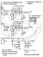
Each channel of the headbanger is almost exactly the same as the other amp you built, except for the parts circled in red. Those new parts should'nt make it oscillate, though. The 10uF capacitor from pin 7 to earth is to reduce hum if you're using a mains power supply. The other capacitor and resistor give the amp some extra gain, but also make distortion a bit worse.
The layout in that tutorial you linked to is a mess anyway, so why not just build it the same way you did the other one?
The most important thing is probably the capacitor you added last time that fixed the oscillation.
The layout in that tutorial you linked to is a mess anyway, so why not just build it the same way you did the other one?
The most important thing is probably the capacitor you added last time that fixed the oscillation.
Attachments
yup, sure bonsai
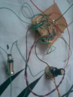
uploaded (though i guess the images wont help much)
also, i am getting good sound from the left and right channels when separately run.(as in left channel ground disconnected, right channel grounds connected, input inro right channel, and i get cool sound on right channel). only when i have to run them together is there a problem.
please note "Grounding is the only problem here" (i dont know what to do with the grounds in this particular circuit).when right channel grounds and right channel grounds are connected together, there is oscillation. as in the schematic with the red circles.
please help me guys.
also, godfrey, please note the 470microfarad cap and the 0.1microfarad cap in the battery circuit.i am surely not missing the 0.1microfarad cap this time.
Attachments

Last edited:
Everyone's problem is that we call everything "Ground".
Most of these wires/connection are the return of a Flow and Return Pair.
They should be run as a pair from the Source to the Receiver.
The power supply to your 386 is a pair, +ve Flow and 0V return. Run these as a pair.
The speaker feed is also a pair. Speaker Flow and Return as a pair from amp to terminals. But here we have our first exception. Do not take the Speaker Return onto the PCB, unless the PCB has the Main Central Audio Ground on board. Multi-channel amplifiers usually have the amps on different PCBs. These must have a separate Main Central Ground and Speaker Return goes here after it arrives at (but not connected) the PCB.
Then consider which returns need to be referenced to a common reference voltage. Use a main Central Audio Ground for this common voltage reference.
- Status
- This old topic is closed. If you want to reopen this topic, contact a moderator using the "Report Post" button.
- Home
- Amplifiers
- Chip Amps
- Headbanger Grounds Trouble