Hi,
My friends have purchased few LM4780 ICs and he want a 7.1 amp with it. So asked me to make a very compact PCB for this IC.
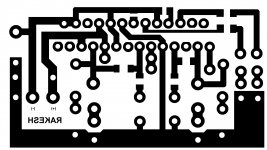
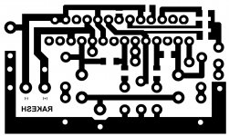
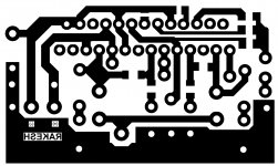
So i have made on with single layer PCB. PSU is on different PCB with 2x10000uf caps.
All resistance (except Zobel ones) are surface-mount on the bottom of the PCB.
Please have a look and give your advice for any improvement.
This is a stereo PCB for all 7 channels and i am working for one parallel for subwoofer.
Thanks
Rakesh Sharma
My friends have purchased few LM4780 ICs and he want a 7.1 amp with it. So asked me to make a very compact PCB for this IC.
So i have made on with single layer PCB. PSU is on different PCB with 2x10000uf caps.
All resistance (except Zobel ones) are surface-mount on the bottom of the PCB.
Please have a look and give your advice for any improvement.
This is a stereo PCB for all 7 channels and i am working for one parallel for subwoofer.
Thanks
Rakesh Sharma
Attachments
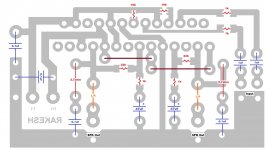
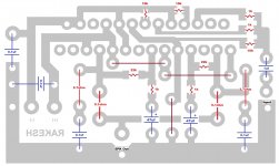
Is the ground from the PSU PCB the unmarked point near your name? If so, that's probably one of the worst places it could be for sound quality  For optimum sound, I suggest your power supply doesn't use a centre-tapped transformer - two (separately rectified) secondaries would be better.
For optimum sound, I suggest your power supply doesn't use a centre-tapped transformer - two (separately rectified) secondaries would be better.It seems OK to use a ground bus for the small signals, but do not connect the dirty grounds (speaker return, zobel and decoupler ground return) to that bus. Make the pads bigger to increase the adhesive if you are going to solder the wires directly to the PCB. Take a look of the LM4780 datasheet, the grounding topology is more or less like that.
that is useful information that we rarely see......I have just done so and i can report it was well worth the extra effort.
Similarly, reports on efforts that do not work are equally useful.
Thanks to Andrew T
My last post was from imformation Andrew T posted to another newbie.
Thanks Andrew i managed to fit 2.5 mm caps with only 15 mm length of wide track to main ground . So far Im thinking most anyone can get a chipamp to work but with a little more effort and lots of reading you can turn it into somthing i would say quite special sounding and with the lm3886 lack of bass naa lack of boom wow i can hear textures and timbres and most of all emotion in my music. and belive me if there is deep powerfull base in a track you will hear it . Right thats it from me as you can tell im buzzing not the amp lol.
Woow... Thank you all for your kind views. As a newbie in DIY Audio amp hobbie this is a super push.
My Psu was a Center tapped type PSU with one bridge, but now i will change it with two seprate rectification section and yes ground track is the bottom one (under my name "RAKESH")
As per the grounding topology and moving 0.1uf cap closer, this is a difficult task, since i have to make the circuit PCB as small as possible.
Can i shift Zobel from PCB to Speaker socket terminials ?
The finished amp will be used as 7.1 amp, placed on the back plate of a subwoofer. Making a subwoofer with 7.1 output.
Amp will be running with 20v +- and 4ohms load, powered by a 10amp transfromer for front, side ,rear and center channel and another 4 amp transformer for Sub amp only.
Any more possibilities for improvement.... please suggest.
Thanking
Rakesh Sharma.
- It is always recommended to avoid rectangular traces. Curves or 45° angles are better.
Why?
(I think I know the answer, just want to hear what you have to say...)
Strange reasoning, but okay.
- Avoid reflections that may superimpose on the signal. Even if you think the frequencies involved are too low for it to make a difference.
- Keep the traces as short as possible. A right angle (or worse a sharp angle) produces a longer trace than a curve or two 45 ° angles.
- Reduce inductance. A right angle produces a higher inductance than a curve or two 45° angles. Even if the additional inductance is so small that you may be tempted to think it won't affect audible frequencies, it is simply good design practice.
- Keep the cross-section constant. If you think about the analogy between current and water, you will easily understand, why.
- Heed the advice of university professors and/or experienced designers and/or textbooks. There is usually a reason why they teach or do things in a certain way.
- It costs the same and looks better.
you could have a look at one of the threads I replied to and my completed amp in the gallery section, however my amp is a parallel configuration.
http://www.diyaudio.com/forums/chip-amps/79303-chip-amp-photo-gallery-220.html
http://www.diyaudio.com/forums/chip-amps/208793-improved-lm3886-power-amp-shine7-4.html
For a parallel configuration resistors should be very carefully matched else you'll end up using only one channel of the IC, besides you'll get slightly more offset at output.
The parallel situation with non-matched resistors is a fair degree worse than you intimate. You could end up with the two amps fighting each other so that the two in parallel do considerably worse than a single channel on its own.
Yes parallel configuration is a lot more challenging, but I managed to make mine work and it stays fairly cool. You can't be sure though, if both the amps are sharing equally. My offset is only around 8mV.
Last edited:
- Status
- This old topic is closed. If you want to reopen this topic, contact a moderator using the "Report Post" button.
- Home
- Amplifiers
- Chip Amps
- Audio Experts advice on LM4780 PCB