TDA7293 parallel BTL mono power Amplifier borad 350W - eBay (item 120595963571 end time Oct-12-10 07:58:28 PDT)
Well I just ordered a couple of these boards on a whim and i'm curious about a few things.
1. Will my 2x20 VAC 400VA trafo work and if so, how low of an impedence will i be able to drive?
2. Are 2 10000 mf filter caps enough? I have two DNMs which were expensive and don't wanna buy another 2 or add cheaper ones.
The impedance you can drive is more a function of the current capability of the chips than of the transformer. 20V and 7% regulation would give you about +/- 29V off-load. You'd then be able to swing up to +/-52V in very short bursts - this is a peak power of 670W into 4R. I'd not want to use bigger than 10,000uF caps on a 400VA transformer myself.
Please post some photos of what arrives - I'd be very interested.
The amount they charge is half what I'd expect to pay wholesale locally so I'm wondering if the company depends of fake parts to break even.
Of course, it would be unjust, unfair and wrong of me to accuse them of anything apart from amazing good value without inspecting the parts that ship.
If it all works and the result is good, I'm going to be shopping even more from China in the near future, but if something blows up without warning, I won't be all that surprised. I'm probably just paranoid.
abraxalito: Thanks, their page states 350watts into 4ohms. It just strikes me as odd that most of the single chip boards on there ask for just as much voltage or more, for quite a lower output wattage. But then again, i don't know much about working this stuff out, that's why i'm asking here.. lol.
random007: I'll borrow a good camera and take a few photos when they arrive. Should be 10 to 20 business days. Do you know how to tell if the components are fake? And if they are fake does that mean sound quality will be lower? I'd liek to assume since they're in China, which is where the original parts are probably made anyway, these guys can just get them at a much lower cost than us. And that would not surprise me considering what these guys on ebay charge to assemble a typical board ($6 or something). So we shall see.
random007: I'll borrow a good camera and take a few photos when they arrive. Should be 10 to 20 business days. Do you know how to tell if the components are fake? And if they are fake does that mean sound quality will be lower? I'd liek to assume since they're in China, which is where the original parts are probably made anyway, these guys can just get them at a much lower cost than us. And that would not surprise me considering what these guys on ebay charge to assemble a typical board ($6 or something). So we shall see.
abraxalito: Thanks, their page states 350watts into 4ohms. It just strikes me as odd that most of the single chip boards on there ask for just as much voltage or more, for quite a lower output wattage. But then again, i don't know much about working this stuff out, that's why i'm asking here.. lol.
random007: I'll borrow a good camera and take a few photos when they arrive. Should be 10 to 20 business days. Do you know how to tell if the components are fake? And if they are fake does that mean sound quality will be lower? I'd like to assume since they're in China, which is where the original parts are probably made anyway, these guys can just get them at a much lower cost than us. And that would not surprise me considering what these guys on ebay charge to assemble a typical board ($6 or something). So we shall see.
Comparing the physical units to known genuine ones is the only way I know of to tell the difference... at least without trying to split the unit's case open and look at the silicon wafer itself! People (mad, strange and very dexterous people) have done that.
All the fake parts I've heard of appear to be high power transistors where the silicon dies of lower powered and cheap components have been repackaged to look like more expensive units. Fake components burn fairly quickly because the cheap silicon is vastly overloaded even when the genuine component should be well within spec.
I've not yet run into any reports of fake amplifier chips: possibly due to their complexity vs single transistors. Take heart - I'm being paranoid when I voice a concern that these cheap kits have to have something dodgy about them - it's unfounded apart from the amount being charged for them which is hardly evidence.
Much of the fake transistor racket is disturbingly professional (though, amusingly, many have simple yet glaring typo errors!). It looks like
most come from India not China.
Last edited:
abraxalito: Thanks, their page states 350watts into 4ohms.
That's the continuous, RMS power, given a big enough transformer. I think its a little optimistic, not very - I think the datasheet is a bit optimistic and I guess they got the power by taking the figure for a single chip and multiplying by 4.
It just strikes me as odd that most of the single chip boards on there ask for just as much voltage or more, for quite a lower output wattage.
My guess is - the majority of boards on there are not bridged. Bridging doubles the output swing and therefore quadruples the power.
I agree with random btw - the price looks spectacularly low. I've heard there are plenty of fake TDAs floating around, but I haven't definitely found one... Yes, parts prices in China are considerably lower than the small quantity prices from western distributors. I bought some TDA7293 a couple of years ago, I think the price was under $2. Have yet to try them so no idea if they're fake...

670W instantaneous peak power is a bit misleading. A meaningful and reliable measure of the maximum power output of an audio amplifier - or the power handling of a loudspeaker - is continuous average sine wave power. When you see '100Watt amplifier' on the forum here, what is meant is 100W continuous average sinewave power (often called 100W RMS), which is equal to 200W instantaneous peak power. Instantaneous peak power is a pretty meaningless term and is rarely used.
w
w
Instantaneous peak power is a pretty meaningless term and is rarely used.
Its by no means 'pretty meaningless' - it means what it says. Additional meaning could be had from saying how long this 'instant' lasts though.
<edit> It has occured to me that perhaps you meant 'pretty meaningless in relation to how loud it will sound in practice' in which case yes, I agree. Continuous average power is a better measure for that, but still has shortcomings.
Continuous average power, while useful for engineers testing amps into resistive loads (and thereby for CE/UL mark safety testing) isn't particularly useful for finding out how loud an amp will play when driving music into real loudspeakers. That's because music has a crest factor considerably higher than that of a sinewave and because the load a speaker presents is reactive and varies with frequency.
Last edited:
It is important to note that achievable power does not only depend on supply voltage and load impedance, but also on heatsinkabilty. The datasheets states that you should not ask for more than 50-60 W output power per IC in normal class AB mode under normal conditions due to thermal resistance. It recommends e. g. a ±25 V supply for a bridged amplifier connected to an 8 Ohm load.
±29 V on a bridged amplifier that feeds a 4 Ohm load lead to ~170 W of heat dissipation. That is a lot even when it is spread across four ICs.
Anyhow, wouldn't it make more sense to use 4 ICs in parallel for a 4 Ohm load than in bridge-parallel configuration?
±29 V on a bridged amplifier that feeds a 4 Ohm load lead to ~170 W of heat dissipation. That is a lot even when it is spread across four ICs.
Anyhow, wouldn't it make more sense to use 4 ICs in parallel for a 4 Ohm load than in bridge-parallel configuration?
Yeah I'm kinda lost. Is the configuration of the board in question parallel or bridge-parallel?
I did come across a thread earlier today where someone mentioned that there are 'plently of fake TDA's floating around' and apparently TDA7293s especially.
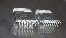
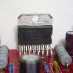
So, I've attached two images. One is a shot of the chip from basically the same board from china by another seller, this one just happens to have a hi res picture. I'm gonna assume it's the same chip im getting. The price is Roughly the same too. The other photo is a USA (top ebay) seller of allegedly genuine chips at $4 a piece (for the chip). They obviously look different. So according to the method of visually comparing them, the chinese one must be fake! However, isn't it possible they are just different versions? So my question still remains.. how do you tell a fake chip? I would also like to know what's so bad about the 'fake' ones. I suppose an e-mail to ST might help, but i also might get a biased answer.
The pic with the two chips is the 'genuine' one.
I did come across a thread earlier today where someone mentioned that there are 'plently of fake TDA's floating around' and apparently TDA7293s especially.
So, I've attached two images. One is a shot of the chip from basically the same board from china by another seller, this one just happens to have a hi res picture. I'm gonna assume it's the same chip im getting. The price is Roughly the same too. The other photo is a USA (top ebay) seller of allegedly genuine chips at $4 a piece (for the chip). They obviously look different. So according to the method of visually comparing them, the chinese one must be fake! However, isn't it possible they are just different versions? So my question still remains.. how do you tell a fake chip? I would also like to know what's so bad about the 'fake' ones. I suppose an e-mail to ST might help, but i also might get a biased answer.
The pic with the two chips is the 'genuine' one.
Attachments
That board certainly looks to be bridged-parallel.
Whilst I've heard the stories (from this forum I think) I have no evidence so far that I've bought any fakes. Reflecting on it, I'd say random is right - the fakes there's evidence for are repackaging of smaller die. The TDA die is dominated by the output MOSFETs (from memory) - cloning it with smaller output devices would require vast technical ability. The only chance I can think of to clone it whilst still operating like an amplifier would be to substitute a much cheaper chip amp die (like a TDA2030). Doing this would leave various functions of the TDA unworking (muting for instance). The acid test would be if the part survives the specified 120V - no other chip amp I'm aware of his this high PSU voltage spec.
I have parts which look almost identical to the 'fake' one in your picture, I also have parts which look different to both (probably older production). I think the only definitive way to tell a fake is to break it apart and examine the die. But for me, if it works just like a 'real' TDA, I don't care if its 'fake'
Abraxalito: Yeah, i did see a couple pictures where they look different to both of those too. Also, one indication that there is nothing wrong with these chips is the fact that they're posting giant hi-res pictures of them. If they don't blow up and sound anything like my tweaked out tda1514's before i fried them i'll be a happy man.
With the ±29V rails and unbridged, the output would be around 85W. 4 ICs in parallel would certainly be overkill for this power level.
Correct. It only makes sense with a higher supply voltage. On the other hand bridge-parallel only makes sense with a lower supply voltage. You need a different power supply either way, so why not use the one that makes more sense?
Also, one indication that there is nothing wrong with these chips is the fact that they're posting giant hi-res pictures of them.
If you could detect fakes by simply looking at them, it would be pretty easy to close down the market for fakes. And the manufacturers don't help by making them or having them made in different locations on different machines with differents cases and different prints on them. They also improve their designs without informing the DIY community, so even opening up the case and finding differences does not necessarily put you in a position to decide which one is fake.
What makes you think they will send you the ICs from the hi-res pictures anyway?
If they don't blow up and sound anything like my tweaked out tda1514's before i fried them i'll be a happy man.
If they are genuine they should sound better. And even the genuine parts seem to have a tendency to blow up. In a German forum you read a lot about people that replaced their TDAs several times before they got one working. And there was also a thread here in the Forum about somebody who has a Jeff Rowland amp with 48(!) TDA7293s inside and quite a bunch of them stopped to work due to some problem with the mute pin. So they seem to be a bit more sensitive than e. g. the LMs.
Correct. It only makes sense with a higher supply voltage. On the other hand bridge-parallel only makes sense with a lower supply voltage. You need a different power supply either way, so why not use the one that makes more sense?
Well, because I want to use the transformer that i have which is a really nice quality Plitron. I'd more likely be scrapping the cheap boards and getting a different module rather than replacing the power supply if something doesn't work.
Why does the page clearly state the voltage as +/-30 - 35 volts DC then? Mine is already below that. What voltage do you think is ideal for this board?
If you could detect fakes by simply looking at them, it would be pretty easy to close down the market for fakes. And the manufacturers don't help by making them or having them made in different locations on different machines with differents cases and different prints on them. They also improve their designs without informing the DIY community, so even opening up the case and finding differences does not necessarily put you in a position to decide which one is fake.
What makes you think they will send you the ICs from the hi-res pictures anyway?
Nothing makes me think that. I was making an assumption for comparison's sake. And as random said, it would be wrong to assume the seller is being deceiving in some way without having prior experience with them. But since you say there is no way to tell the bad ones from the good ones, even by having them in front of you, there is no point in trying. And i'm fine with that, for $70 assembled, they're worth a try.
I wonder which Jeff Rowland amp that is. I know of the Concerta and Model 10 i believe that have chip amps but did not realise they had one with 48 chips inside... that's amazing
Why does the page clearly state the voltage as +/-30 - 35 volts DC then?
That is a question only they can answer.
What voltage do you think is ideal for this board?
The datasheet recommends ±25 V for a comparable application (two bridged ICs with 8 Ohm load is similar to four bridged ICs with 4 Ohm load) and should in theory be good for 300 W with an adequate power supply.
for $70 assembled, they're worth a try.
That's the spirit.
I wonder which Jeff Rowland amp that is. I know of the Concerta and Model 10 i believe that have chip amps but did not realise they had one with 48 chips inside... that's amazing
http://www.diyaudio.com/forums/chip-amps/123956-jeff-rowlands-mc6-problems.html#post1523602
It has TDA7294 instead of TDA7293, but the only difference between those two is the supply voltage range.
Correct. It only makes sense with a higher supply voltage.
With your suggestion the amp chips are seeing a load of 16R each. The way I'm reading the datasheet, that's not an ideal load. Looks like the output into 16R is voltage limited, whereas the optimum load is power limited.
The datasheet says:
Thanks to the wide voltage range and
to the high out current capability it is able to supply
the highest power into both 4W and 8W loads.
On the other hand bridge-parallel only makes sense with a lower supply voltage.
That supply voltage looks fine to me. My datasheet says that a chip will dissipate 50W at a 70oC case temp. Four chips therefore can handle 200W, you've said with those supplies they need to handle 170W. So I don't see a problem - bearing in mind this is worst case continuous power and real music has a higher crest factor than a sinewave.
If they are genuine they should sound better. And even the genuine parts seem to have a tendency to blow up. In a German forum you read a lot about people that replaced their TDAs several times before they got one working. And there was also a thread here in the Forum about somebody who has a Jeff Rowland amp with 48(!) TDA7293s inside and quite a bunch of them stopped to work due to some problem with the mute pin. So they seem to be a bit more sensitive than e. g. the LMs.
The first amp I built with TDA7294 I blew up because I tried decoupling the signal stage power supply with series resistors. There are circuits out on the net which still show similar decoupling. This blows up chips. Once I realised this, I haven't blown up another TDA and I built several prototypes at different stages of development.
Looks like the output into 16R is voltage limited, whereas the optimum load is power limited.
With 4 Ohm the load is current limited, so by your definition non-ideal either.
What is power limited anyhow? The load where voltage and current limit happen at the same time? And do you insist on resistive speakers to have the optimum load across the entire frequency range as well?
The optimum load to what purpose anyhow? To tickle the last mW from each TDA? In the end the power will be limited, so what difference does it make, whether that is due to voltage, current, power, temperature or whatever factor?
That supply voltage looks fine to me. My datasheet says that a chip will dissipate 50W at a 70oC case temp.
Mine says
"a high efficiency system is needed in those cases where the continuous RMS output power is higher than 50-60 W" High Efficiency System being a class H setup.
That recommendation is based on the heat dissipation. To keep the case at 70 °C with 170 W Pd at 25 °C ambient the total thermal resistance must be below 0,265 K/W. The TDA7293 has already 1 K/W on its own.
With 4 Ohm the load is current limited, so by your definition non-ideal either.
Well, let's check to see if your assertion holds up. Since the current limit is typically 6.5A per chip we'd get 13A peak into 4R which is 52V. Given a supply of ±29V nominal, we won't reach this swing in practice owing to power supply sag on-load. It would need regulation and ripple together to contribute zero drop from the nominal. So no, we're not (unless we have a regulated supply, which we don't) going to reach the current limit.
What is power limited anyhow? The load where voltage and current limit happen at the same time?
Where the limitation is due to dissipation in the IC rather than voltage or current limits.
And do you insist on resistive speakers to have the optimum load across the entire frequency range as well?
I make no insistence at all. Just comparing different topologies into a 4R resistive load as the speaker is unknown.
The optimum load to what purpose anyhow? To tickle the last mW from each TDA?
Pretty much yeah. That's what engineering is about as far as I'm concerned - making optimum use of resources. If we factor in the quiescent dissipation (50mA draw) then the lower voltage bridged gets an even bigger advantage.
In the end the power will be limited, so what difference does it make, whether that is due to voltage, current, power, temperature or whatever factor?
No amplifier that I've heard of has unlimited power. So here I really do not understand what your argument is.
Mine says
"a high efficiency system is needed in those cases where the continuous RMS output power is higher than 50-60 W" High Efficiency System being a class H setup.
I thought the amp was going to be used to play music, not continuous sinewaves? Or have I misunderstood?
That recommendation is based on the heat dissipation. To keep the case at 70 °C with 170 W Pd at 25 °C ambient the total thermal resistance must be below 0,265 K/W. The TDA7293 has already 1 K/W on its own.
All the more reason to choose the solution which gives rise to the lowest power dissipation per watt of output then.
Where the limitation is due to dissipation in the IC rather than voltage or current limits.
Language barrier. For me that is thermal limitation.
That's what engineering is about as far as I'm concerned - making optimum use of resources.
That is only one small part of what engineering is about where I come from. Also the definition of optimum use of ressources seems to be different where you live and/or work. Here it is to design as exactly as possible for the necessary power. Designing for the highest possible power without need is considered a waste of ressources.
No amplifier that I've heard of has unlimited power. So here I really do not understand what your argument is.
I gave none. I don't understand yours. If the amplifier is limited anyhow, what does it matter which is the limiting factor as long as there is enough power?
All the more reason to choose the solution which gives rise to the lowest power dissipation per watt of output then.
That is certainly not the solution with your definition of an ideal load, because that would lead to the highest possible dissipation.
- Status
- This old topic is closed. If you want to reopen this topic, contact a moderator using the "Report Post" button.
- Home
- Amplifiers
- Chip Amps
- some help on TDA7293 boards off Ebay