hello,
Douglas Self recently co-authored a gridAmp in Elektor using a 4x8 NE5532 grid. There are thus 64 audio opamps in total, each able to deliver 30mA individually so 1.92 amp when paralleled. The 8 ohm load gets thus raised to a 15.36 V potential with a + 18V and a - 18 V supply. Max power is thus close to 15 watt RMS into 8 ohm. One may expect a 1 kHz distorsion in the order of 3ppm to 5ppm (0.0003% to 0.0005%) if the PCB is carefully designed.
The 5532 OpAmplifier, part 1 - ELEKTOR.com | Electronics: Microcontrollers Embedded Audio Digital Analogue Test Measurement
I would like to discuss the feasibility of a more advanced gridAmp delivering 9 watt RMS into 8 ohm with less than 1ppm (0.0001%) distorsion at 1 kHz. This is maybe possible using a grid of quad audio opamps in 14 pin packages like OPA1644, OPA4134 or LME49740. The 9 watt / 8 ohm signal is 24V peak peak : ((12 V x 0.707)**2) / 8 ohm = 8.997 watt. Please advise the recommended measuring equipment, being analog or digital or anything else.
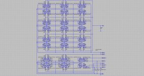
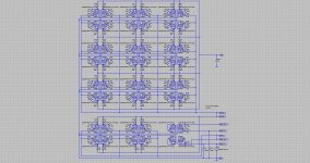
For the sake of simplicity I have used LTspice to test some ideas about routing a PCB with a 3x3 grid. The grid can easily be extended to 4x4 or more. A 4x4 grid would produce the same power as the above Elektor-Self gridAmp design. I have modelled the opamps using a Laplace in the definition of a dependent voltage source. The opamp input offset is modelled using a DC voltage source in the input. This modelization is thus useless regarding distorsion. The aim of this modelization is to accurately simulate the imbalance currents caused by DC offsets and high-frequency poles differences. It also helps organizing the layout for optimizing the PCB design. Avoiding loops, keeping the layout dense, getting an untouched ultra-quiet ground, and so on.
I have generated two different approaches.
The first approach is copied from Douglas Self approach, using a grid of paralleled non-inverting unity gain buffers at the output. The resulting circuit is very easy to route on a PCB. There are almost no passive components in such a gridAmp. The big drawback is the common-mode voltage, stressing the opamps input stages. With this layout, the opamp don't deliver the best. However, with OPA1644, OPA4134 or LME49740, it could be that this simple arrangement is okay for delivering the 1kHz 1ppm 24V pp output signal into a 8 ohm load.
The second approach uses a grid of parallelled inverting amplifiers. The resulting circuit is less easy to route on a PCB. There are many resistors. They need to be 0.1% precise, but this is not an issue nowadays with Panasonic inexpensive SMT0805 0.1% resistors. This configuration is supposed to provide the best results, as the only common mode is in the optional input buffer. If you omit the input buffer, you end up with a zero common mode design. Distorsion should be minimal.
A 1ppm distorsion figure is only meaningfull if the noise floor is kept below the harmonics. For assessing a THD, you need the harmonics emerging from the noise floor. Excessive noise could thus prevent reaching the 1ppm target. In his gridAmp design, Douglas Self paid a lot of attention to noise, especially in the input stage. I don't know if this is mandatory when using OPA1644, OPA4134 or LME49740 opamps instead of NE5532 opamps.
I don't know if SMT opamps can be used. What will be the dissipation of each integrated circuit when delivering 9 watt on 8 ohm, including the quiescient currents and output imbalance currents ? If SMT opamps can't be used, we face a little difficulty as it seems that the OPA4134 and LME49740 are the only quad audio amps available both in SMT (SO-14) and through-hole (DIP-14).
If the SMT dissipation capability is exceeded with a 8 ohm load, the SMT versions can be used for trying building a 1ppm headphone gridAmp. Are there 1ppm headphones amps on the market ? Would be a 2x2 grid okay, hence 16 paralleled opamps ?
See attached LTspice diagrams.
Anyway, I feel Douglas Self NE5532 gridAmp deserves attention. I intend purchasing a few Elektor PCBs (they are available in the webshop) as references, for some listening tests and possibly also as reference base for (improved ?) versions using the OPA1644, OPA4134 or LME49740.
Steph
Douglas Self recently co-authored a gridAmp in Elektor using a 4x8 NE5532 grid. There are thus 64 audio opamps in total, each able to deliver 30mA individually so 1.92 amp when paralleled. The 8 ohm load gets thus raised to a 15.36 V potential with a + 18V and a - 18 V supply. Max power is thus close to 15 watt RMS into 8 ohm. One may expect a 1 kHz distorsion in the order of 3ppm to 5ppm (0.0003% to 0.0005%) if the PCB is carefully designed.
The 5532 OpAmplifier, part 1 - ELEKTOR.com | Electronics: Microcontrollers Embedded Audio Digital Analogue Test Measurement
I would like to discuss the feasibility of a more advanced gridAmp delivering 9 watt RMS into 8 ohm with less than 1ppm (0.0001%) distorsion at 1 kHz. This is maybe possible using a grid of quad audio opamps in 14 pin packages like OPA1644, OPA4134 or LME49740. The 9 watt / 8 ohm signal is 24V peak peak : ((12 V x 0.707)**2) / 8 ohm = 8.997 watt. Please advise the recommended measuring equipment, being analog or digital or anything else.
For the sake of simplicity I have used LTspice to test some ideas about routing a PCB with a 3x3 grid. The grid can easily be extended to 4x4 or more. A 4x4 grid would produce the same power as the above Elektor-Self gridAmp design. I have modelled the opamps using a Laplace in the definition of a dependent voltage source. The opamp input offset is modelled using a DC voltage source in the input. This modelization is thus useless regarding distorsion. The aim of this modelization is to accurately simulate the imbalance currents caused by DC offsets and high-frequency poles differences. It also helps organizing the layout for optimizing the PCB design. Avoiding loops, keeping the layout dense, getting an untouched ultra-quiet ground, and so on.
I have generated two different approaches.
The first approach is copied from Douglas Self approach, using a grid of paralleled non-inverting unity gain buffers at the output. The resulting circuit is very easy to route on a PCB. There are almost no passive components in such a gridAmp. The big drawback is the common-mode voltage, stressing the opamps input stages. With this layout, the opamp don't deliver the best. However, with OPA1644, OPA4134 or LME49740, it could be that this simple arrangement is okay for delivering the 1kHz 1ppm 24V pp output signal into a 8 ohm load.
The second approach uses a grid of parallelled inverting amplifiers. The resulting circuit is less easy to route on a PCB. There are many resistors. They need to be 0.1% precise, but this is not an issue nowadays with Panasonic inexpensive SMT0805 0.1% resistors. This configuration is supposed to provide the best results, as the only common mode is in the optional input buffer. If you omit the input buffer, you end up with a zero common mode design. Distorsion should be minimal.
A 1ppm distorsion figure is only meaningfull if the noise floor is kept below the harmonics. For assessing a THD, you need the harmonics emerging from the noise floor. Excessive noise could thus prevent reaching the 1ppm target. In his gridAmp design, Douglas Self paid a lot of attention to noise, especially in the input stage. I don't know if this is mandatory when using OPA1644, OPA4134 or LME49740 opamps instead of NE5532 opamps.
I don't know if SMT opamps can be used. What will be the dissipation of each integrated circuit when delivering 9 watt on 8 ohm, including the quiescient currents and output imbalance currents ? If SMT opamps can't be used, we face a little difficulty as it seems that the OPA4134 and LME49740 are the only quad audio amps available both in SMT (SO-14) and through-hole (DIP-14).
If the SMT dissipation capability is exceeded with a 8 ohm load, the SMT versions can be used for trying building a 1ppm headphone gridAmp. Are there 1ppm headphones amps on the market ? Would be a 2x2 grid okay, hence 16 paralleled opamps ?
See attached LTspice diagrams.
Anyway, I feel Douglas Self NE5532 gridAmp deserves attention. I intend purchasing a few Elektor PCBs (they are available in the webshop) as references, for some listening tests and possibly also as reference base for (improved ?) versions using the OPA1644, OPA4134 or LME49740.
Steph
Attachments
Last edited:
let's assume a 3x3 grid of single opamps giving 9W into 8r0.
Each opamp sees the loading as 1W into 72r0.
That requires 12Vpk and 167mApk.
Look up the opamp datasheet and find what it says about 72r loading and about 12V @ 167mA.
Now consider that a power amp MUST be capable of providing at least double the resistive load current and preferably three times the resistive current.
Let's see if a 4x4 grid can manage that.
0.563W into 128r requires 12Vpk and 94mApk.
In to a reactive speaker we require at least 188mApk and preferably 280mApk.
What does the datasheet say about that?
Now try an 8x8 grid. I find a preferred maximum current of 91mApk.
Now swap from the 8ohm speaker to a 300ohm headphone with a maximum voltage output of 5Vpk. Try the numbers.
Last edited:
AndrewT,
numbers are numbers. Dry numbers. When we specify 9 watt into 8 ohm, we really mean 9 watt into 8 ohm. We don't mean 9 watt plus 1000% headroom into a 8 ohm load dropping to 6 ohm DC with 10µF capacitance in parallel. You don't get an airplane flying by adding percentages and percentages. I you want more current, or another load impedance, just ask and we'll see what kind of gridAmp needs to be designed. Any kind of gridAmp can be designed, from 3x3 to 3Megx3Meg. It all depends your taste and goodwill. No offense.
Cheers,
Steph
attributing the thought of
I took the time to show by example what the grid amp arrangement is asking each opamp amp to deliver.
You should take the time to follow that example and see if you agree or disagree with the method of assessing suitability.
If you can't be bothered, then don't ask.
to my post is offensive.We don't mean 9 watt plus 1000% headroom
I took the time to show by example what the grid amp arrangement is asking each opamp amp to deliver.
You should take the time to follow that example and see if you agree or disagree with the method of assessing suitability.
If you can't be bothered, then don't ask.
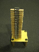
I started a similar project some time ago but never found the motivation to finish it. I was going for 20 OPA2134 per channel. It was to be dubbed "The Leaning Towers of OPA".
I can't see myself ever starting the other stack. Maybe I will finish just this one stack and make a headphone amp out of it instead.
I can't see myself ever starting the other stack. Maybe I will finish just this one stack and make a headphone amp out of it instead.
Attachments
AndrewT,
what loudspeaker do you need to drive ? Can you attach the impedance diagram ? I definitely know that the I/V locus is of importance. You need to understand that we need dry numbers before proceeding, before assessing how many quad opamps need to be paralleled when driving a real-world load. Both of us, we know how (poor) amps can sound when simply (stupidly ?) adding headroom percentages here and there before even considering the dry figures.
With a 20V/µs slew-rate, a 5 MHz small signal bandwidth, and a possibly 1ppm THD, the gridAmp looks like an interesting bukding block. How to use it ?
As previously explained, with 17 Volt or 18 Volt supplies, the linearity will be preserved with a 12 Volt voltage excursion referred to ground, even when opting for the (simpler) non-inverting unity gain buffer output stage.
Say you want to be able to handle a 2 ohm load. The current is thus 6 amp.
Say that one opamp can deliver 25 mA. You thus need 240 opamps. There are four opamps in a 14-pin package. You thus need 60 14-pin packages. You may organize them in a 8x8 grid (64 14-pin packages). A 8x8 gridAmp is still very compact, especially when using SMT devices. As previously explained, the 3x3 gridAmp example is only there for showing the concept and the way the PCB layout may be organized for ensuring a clean, quiet ground.
The power on a 2 ohm load is ((12*0.707)**2)/2 = 36 watt. If you bridge the load, using four such units, the power becomes 144 watt. With a 20V/µs slew-rate, a 5 MHz small signal bandwidth, and a possibly 1ppm THD. Do you know many power amplifiers delivering such spec ? For the cooling, you may use a CPU cooler and fan applied on the grid, with or without heat pipe, with or without liquid cooling. The thermal stress gets evenly spread onto a big surface. There are no hotspots.
Cheers,
Steph
Last edited:
Wait untill we produce PCBs. Or SMT-equipped PCBs. What would be your quad audio opamp choice, nowadays ? Your input is valuable.I started a similar project some time ago but never found the motivation to finish it. I was going for 20 OPA2134 per channel. It was to be dubbed "The Leaning Towers of OPA". I can't see myself ever starting the other stack. Maybe I will finish just this one stack and make a headphone amp out of it instead.
Wait untill we produce PCBs. Or SMT-equipped PCBs. What would be your quad audio opamp choice, nowadays ? Your input is valuable.
My quad op-amp of choice is definitely the LME49740. I'm not sure I would really be interested in such a board on serious level though. My experiment with the OPA2134 was really just for the novelty of it.
If I were to make power amplifier of this style I would just use a high current buffer IC like the LME49600. This way you don't have to use as many IC's and the 49600 has excellent specs anyway. I've actually thought about doing this already and have about 30pcs sitting right here on my desk.
It got never said nor suggested that a 3x3 grid would ever handle 9 watt. Post #1 is clear enough, stating that the 3x3 grid example is there for illustrating the principle and a possible PCB layout.let's assume a 3x3 grid of single opamps giving 9W into 8r0. Each opamp sees the loading as 1W into 72r0. That requires 12Vpk and 167mApk. Look up the opamp datasheet and find what it says about 72r loading and about 12V @ 167mA. Now consider that a power amp MUST be capable of providing at least double the resistive load current and preferably three times the resistive current.
For 9 watt (12V peak excursion relative to ground, on 8 ohm), you need 1.5 A peak. Knowing each opamp can deliver 25mA (conservative value) or 30mA (limit value), you need 60 opamps or 50 opamps. There are 4 opamps in each package. You thus need 15 quad-opamps or 12.5 quad-opamps. A 4x4 grid provides 16 quad-opamps hence 64 opamps. The 4x4 grid is thus fine for delivering 9 watt RMS into a 8 ohm load. This equivalent to the Douglas Self NE5532 powerAmp design in Elektor, with 32 dual-opamps in a 4x8 grid.Let's see if a 4x4 grid can manage that. 0.563W into 128r requires 12Vpk and 94mApk. In to a reactive speaker we require at least 188mApk and preferably 280mApk. What does the datasheet say about that?
From where do you get this figure ? Each opamp can deliver 25mA (conservative value) or 30mA (limit value). With a 8x8 grid you get 8x8x4 opamps. You thus get 6.4 A peak (conservative value) or 7.68 A peak (limit value). Amazing, isn't ? A 6.4 A peak current on a 12 Volt peak excursion (referred to ground) means a 1.875 ohm load. A 8x8 grid is thus overkill for a 8 ohm load, is overkill for a 4 ohm load, and may be suitable for a 4 ohm bridge-tied load. In a bridge-tied load configuration, with a 4 ohm load, the RMS power is ((24*0,707)**2)/4 = 72 watt RMS.Now try an 8x8 grid. I find a preferred maximum current of 91mApk.
Still no offense. Have a nice day
Steph
Last edited:
Very interesting approach. Do alternate manufacturers produce pin-compatible devices ? The LME49600 can deliver up to 250mA in a quite small package. The metallic tab helps conveying the heat. The PCB will thus act as heat dissipator. A conventional heat dissipator still can be applied on the IC packages. A 4x4 grid would thus provide 4 A peak. This may be okay for a 8 ohm bridge-tied load arrangement delivering ((24*0.707)**2)/8 = 36 watt RMS.If I were to make power amplifier of this style I would just use a high current buffer IC like the LME49600. This way you don't have to use as many IC's and the 49600 has excellent specs anyway.
Farnell Prices (10-99 units) :
LME49600 = 1 x 250mA at 8.77 eur so 35.00 eur per Ampere
OPA4134 = 4 x 25mA at 3.83 eur so 38.30 eur per Ampere
OPA1644 = 4 x 25mA at 6.01 eur so 60.10 eur per Ampere
LME49740 = 4 x 25mA at 9.67 eur so 96.70 eur per Ampere
For a minimal footprint, the only choice is the LME49600. There is no price premium to be paid. The flipside is the absence of second-sources from alternate makers.
When footprint size doesn't matter, the OPA4134 is the wise choice. Upgrades to the more expensive OPA1644 and LME49740 are trivial, being OPA4134 drop-in replacements.
try an 8x8 grid. I find a preferred maximum current of 91mApk.
First let's try to get us on an equal footing.From where do you get this figure ? Each opamp can deliver 25mA (conservative value) or 30mA (limit value). With a 8x8 grid you get 8x8x4 opamps.
I am referring to single opamps, you are referring to quad opamps.
I read the first post as 9W from a 3x3 grid or 4x4 grid. I must have misread that.
Where did I get 91mApk from?
9W into 8r0 is equivalent to 12Vpk and 1.5Apk.
Into a reactive speaker load I stated that the minimum current capability of the amplifier must be at least 2times the resistive load current and the preferred capability be about 3times the resistive load current.
Now to the 8x8 grid of single opamps.
That resistive current of 1.5Apk becomes a preferred demand of 4.5Apk into a reactive speaker load driven by music signals.
4.5Apk spread among 64 opamps comes to 70mApk, not 91mApk as quoted above.
What is the dissipation limit for a single opamp? Is the dual version any different? and the quad version?
Do these differences allow the quad package to run at similar conditions to the single opamp?
I don't think you can run a quad with all 4 opamps in parallel to the same output levels as four separate opamps running in parallel. There is my opinion.
Edit.
using Iq=3.9mA & +-18.3Vdc, I calculate that the quad package will run @ ~31Cdegrees hotter than the single package during no signal (quiescent) conditions.
Last edited:
Very interesting approach. Do alternate manufacturers produce pin-compatible devices ?
Just the Texas Instruments BUF634 which is available in DIP-8, SO-8, TO-220-5, and DDPAK-5.
see which thread wins?
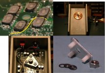
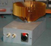
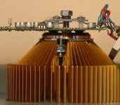
6x TPA6120 dual op amps, rated 400 mA each op amp - parallel pairs biased against each other for Class A push-pull output (a little over 200 mA Class A bias for the headphone amp)
this is sized as a headphone amp so the outputs are cascaded for higher drive V (600 Ohm cans or the insanely low sensitivity AKG K1000)
TPA has exposed Cu power pad meant to be soldered to board for several W dissipation, by soldering "belly up" I contact them to the Cu slug of a pc cooler - running ~ 30 W quiescent total without fan
re arranging the I,V by flat paralleling you could get 2.4A, 15 V peak each channel for ~ 14 Wrms into 8 Ohms Class AB stereo
all up, both channels paralleled as a monoblock the shown components, heatsink should drive down to ~3 Ohms
Attachments
hello AndrewT, using LTspice, I just sketched a few cellAmp designs using 8x paralleled LME49600 in the feedback loop, with a TL071 as controller. I also sketched a swinging power supply for extending the voltage. Looks interesting. I also did some simulations using an ideal TL071 and an ideal OPA134. See the attached .zip.
Attachments
-
cellAmp.zip33 KB · Views: 195
-
 cellAmp TL071 8x LME49600 (58.13 ppm THD) schematic.jpg256.6 KB · Views: 832
 -
 cellAmp Kuroda TL071 8x LME49600 (2.89 ppm THD) schematic.jpg216.6 KB · Views: 788
 -
 cellAmp Kuroda TL071 8x LME49600 with BJT voltage extender (6.37 ppm THD) 2 schematic.jpg229.4 KB · Views: 408
Last edited:
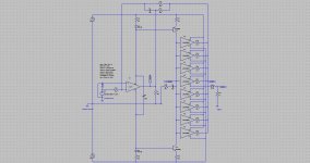
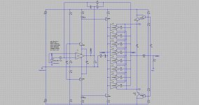
hi jcx, I just discovered your TPA6120 design. Lovely ! What do you mean by cascading them for higher drive V ?
the top is a sketch of cacading op amps for double the V swing - becomes a little complicated
the lower is a sim of one possible bridged floating supply circuit which also doubles Vswing at the cost of requiring a isolated supply (V4 in this sim)
beware of simulating these circuits - the common Boyle op amp macromodel assumes the op amp's output gain stage is connected to spice node 0
this is wrong for floating supply/modulated/bootstrapped supply op amp circuits and can give wrong indications of stable operation where additional compensation is needed
Attachments

Last edited:
hi jcx, many thanks for your feedback.
Feel free to pickup my dedicated opamp models listed in the above cellAmp.zip file in post #15.
The TL071 model is a homemade transistor level model with accurate power supply behaviour. It is instrinsically compatible with your floating supply/modulated/boostrapped supplies.
The TL071_ideal model and the OPA4134_ideal model are homemade ultralinear models (distorsion 0.00 ppm), still accurate regarding the supplies if you pay attention to the external ground, needed as supplementary pin. Open the TL071_ideal model and you will understand what I mean.
Those three homemade models are the only ones able to cope with the Kuroda topology, using the power supply current as signal lines. They are interchangeable. Swapping a TL071 by a TL071_ideal, then by a OPA4134_ideal enables better identifying the THD contributors.
In this other thread http://www.diyaudio.com/forums/chip-amps/174540-doug-selfs-ne5532-power-amp-thoughts-anyone.html nmiljac pointed out a very interesting parallel architecture featuring moderate common mode, global feedback and symmetric distributed class A domain extension. I think I will create some opamps models using LTspice, let us call them hybrid models, having a transistor-level (BJT or JFET) differential input stage fed by a nearly ideal Spice curent source (parallel resistor), a linear 1st order lowpass VAS using a Spice RC network and a voltage-controlled voltage source, and a transistor-level class AB output stage with current limit. With no concerns for the slew-rate, for the sake of simplicity. And, possibly, accurate power supply terminals for embedding them in the Kuroda topology. This should enable better comparisons, as a starting point.
Last edited:
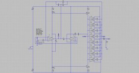
this is the Kuroda_m design. Same as Kuroda, but there is now one opamp used to generate a local ground. This way, the quality of the quiet ground greatly improves. The only connections to the quiet ground are the positive inputs of the opamps, representing very high impedances.
I was expecting getting an inflated THD figure, but this is not the case. The Kuroda and the Kuroda_m exhibit the same THD on simulation. Is there a hidden theorem somewhere ?
More research should be done, using other opamp models.
The interest of this local ground generation still needs to be assessed, comparing the Kuroda and the Kuroda_m when adding copper resistance in the ground paths. There we may see the Kuroda_m being quite insensitive to ground resistance, as an advantage.
Attachments
Last edited:
- Status
- Not open for further replies.
- Home
- Amplifiers
- Chip Amps
- 1ppm gridAMP