I'm in the assembling stage of my 4 channel gainclone. I've followed Peter Daniel's full schematic ( the one with the power supply on it )
So, i rigged up one channel temporarily to make sure i had assembled everything correctly. I seem to remember reading on Nuuk's website that i should attach a 10 Ohm resistor to the speaker outs, then measure for a max of 28ma of DC ( is this correct?)
Anyways, i put a wee .25 watt 10 ohm resistor on the terminals, fired it up, and the resistor went up in a puff of smoke.
I'm off to get a dummy load from radio shack so i can continue testing...but, this actually was a good sign, right? I mean, if the power made it all the way to the speaker terminals and fizzled out the resistor...that's way better than nothing happening at all, right?
Comments?
-Maz
maz,
like pinkmouse said, double check your connections. something else must be wrong....i've had the same thing happen to me that i smoked a bunch of those 1/8 watt resistors. you can check your dc offset voltage w/o the resistors in place, and they should read the same. after i smoked my resistors i found the dc offset to be 0.8 volts!!! no wonder the poor little 1/8 watt resistors go up in smokes!!!
like pinkmouse said, double check your connections. something else must be wrong....i've had the same thing happen to me that i smoked a bunch of those 1/8 watt resistors. you can check your dc offset voltage w/o the resistors in place, and they should read the same. after i smoked my resistors i found the dc offset to be 0.8 volts!!! no wonder the poor little 1/8 watt resistors go up in smokes!!!
Let me explain my setup, then what just happened....
I have 1 plitron 500VA trafo with dual 24v secondaries. ( 500 VA is more than enough for 4 channels, but..i got a good deal on this one. )
Anyways, i built the 2 bridges this morning with MUR860's, and panasonic 4.7uf electros on the bypass. I didn't have a whole lot of faith in my power supply, so a few minutes ago i disconnected the entire power supply from the rest of the amp.
Long story short, i was just measuring the voltages after the bridges...i fired it up, and within 15 seconds ( and while i was working with my multimeter ) the 2 bypass caps just exploded.
They were 50V..... but the last thing i saw on my multi before they exploded was 25ish VDC between the V+ and V0 wires after the bridge...
luckily i had my goggles on.
any advice?
-Maz
maz, I am not sure how good electros are as by-passing caps. the usualy suspects are ceramic discs or plastic caps (polypropylene for example). plus, 4.7u may be a little too big for by-passing (0.01u - 1u is usually what people use, and i personaly like 0.1u).
anyway, in your case, you might have reversed the polarity of the electrolytics.
anyway, in your case, you might have reversed the polarity of the electrolytics.
I used this schematic....and i'm pretty sure i wired the polarity of the caps correctly...its hard to tell now that they are ashen. It has been widely discussed on this forum, however, that Peter Daniel was using the 4.7uf Black Gate caps for bypass....so, per the schematic, i used the similar Panasonic version.
Attachments
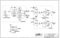
I just realized something :
The panasonic FC series 4.7uf i used is a POLAR cap. The black gate N series 4.7uf is a non-polar electrolytic.
I substituted the black gate with an incompatible part, and explosions ensued.
EDIT : no..that's wrong, i think the part can be substituted, but if you wire a polarized cap like shown above, they will explode....the symbol on the bottom snubber cap is in the right direction, but the top one is backwards...
Can somebody verify this?
-Maz
Magnetmaz said:the symbol on the bottom snubber cap is in the right direction, but the top one is backwards...
Can somebody verify this?
-Maz
you are correct, Maz. the polarity is reversed for the top one.
- Status
- This old topic is closed. If you want to reopen this topic, contact a moderator using the "Report Post" button.
- Home
- Amplifiers
- Chip Amps
- So i fizzled my test resistor....