Hi folks,
Taken a look at other threads here, but wanted to pose this specific question regarding source output impedance and the following load. Specifically w/ a LM3875 based gainclone I am building. I have built lots of stuff now, but still not very knowledgeable with electronics.
I believe it is common practice for source impedances to be much lower than their loads, correct? But I wonder if my situation is acceptable or not:
I am planning to use my gainclone without a preamp before it, EXCEPT for my turntable. The turntable will be (ideally) going through a Bottlehead Seduction which I am also building, and which has an output-Z of roughly 5K. I have read that the source load of the gainclone is about 22K.
Will these numbers result in terribly degraded performance? If yes, what sort of device can help the gainclone see a much lower impedance at its input? I don't want to have to add a line-stage, if possible (budget!). Would a buffer help with this? If so, can you recommend a cheap DIY buffer option?
Thanks in advance-- hopefully this isn't too novice a question for you guys!
AT
Last edited:
There are two types of matching input and output impedances. One is power matching which is often done when you couple output transformers to a speaker. The impedances of transformer and speaker should be the same then. The other is voltage matching which is the common practice between source and amp where the source's output impedance should be smaller 1/10 of the amp's input impedance.
In your case of 5k/22k you waste about 18,5 % of the signal strength, because the voltage drops in relation the impedances. E. g. your source gives a 200 mV signal and the amplifier will only see 162 mV at its input.
In your case of 5k/22k you waste about 18,5 % of the signal strength, because the voltage drops in relation the impedances. E. g. your source gives a 200 mV signal and the amplifier will only see 162 mV at its input.
If your gainclone is non-inverting, there's no particular reason you're limited to 22k input resistance. I'd suggest an input resistance of greater than 50k for a source impedance of 5k - along the lines of pacificblue's suggestion. Increasing the input impedance of a non-inverting gainclone can be done by component substitution or by bootstrapping (adding a modicum of positive feedback). Certainly no need to add a buffer in this situation.
Hrm, okay, thanks very much!
This is not something I feel comfortable figuring out on my own, and I have not been able to find much information regarding this issue. I wonder if someone could point me in the right direction for increasing the input impedance of the gainclone? It is the Audio Sector kit; I have included the schematic.
I know this is real basic stuff, as a matter of fact I have calculated these things before now that I look at it, but I cannot for the life of me remember the math. Would you use the voltage divider equation to calculate Zin? Which resistor is the better one to increase so as to not impact the audio?
Thanks again for your help!
AT
Attachments
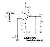
I see this particular schematic is DC coupled - therefore there's already an asymmetry in the impedances seen from the -ve and +ve inputs. Its generally sound practice to equalize these. In this case though because there's already asymmetry, just change the 20k input resistor to 56k. Does the Bottlehead have a series output cap (not familiar with this design)? My guess is, being a valve unit it does, so then there's no need for any input cap on the gainclone.
Ideally this amp would have a DC blocking cap in series with the 620R resistor, along the lines shown in the National datasheet for the LM3875. If you went this route, then the 20k resistor increases in value to 56k and the 620R goes up to 1k6 when the input resistor changes to 56k. This will result in balanced impedances at both inputs and hence the lowest possible DC offset at the output.
Ideally this amp would have a DC blocking cap in series with the 620R resistor, along the lines shown in the National datasheet for the LM3875. If you went this route, then the 20k resistor increases in value to 56k and the 620R goes up to 1k6 when the input resistor changes to 56k. This will result in balanced impedances at both inputs and hence the lowest possible DC offset at the output.
Last edited:
Thanks a million abraxalito!
As an aside, are input impedances completely arbitrary then? I mean, I am sure they aren't, so what are the consequences of changing the 20k to a 56k, for example? The original choice to have the input resistor as 20k was based on what, do you think?
Just trying to learn a little here...
Cheers!
AT
As an aside, are input impedances completely arbitrary then? I mean, I am sure they aren't, so what are the consequences of changing the 20k to a 56k, for example? The original choice to have the input resistor as 20k was based on what, do you think?
Just trying to learn a little here...
Cheers!
AT
Along with a highpass filter and "input impedance", the input resistor also forms a time constant with the DC blocking capacitor. Higher value of input resistor means more chance of getting a "pop" noise at startup when the amp is powered on because the input cap takes longer to charge.
If you have a delayed speaker connection (by means of a relay) then this is a non-issue. But for most general-purpose amps, turn-on pop reduction is the reason input impedance has been standardized to 10k for unbalanced inputs and 20k (2x 10k) for balanced ones. Of course, in DIY designs, you are free to pick any values you wish.
Try this experiment, but do it at low power and with some cheap speakers, you don't want to damage anything expensive. Put a 2 Megohm input resistor and a 330nF input cap. When the amp is turned on, you will see the speaker cones moving forward (or rearward depending on polarity), then back to the center position. This isn't a "pop" anymore, it's a full-blown DC ramp down already, showing the effects of the time constant made by the large input resistor. This is why it is desirable to keep input impedance as low as the source can accept, speakers don't like that kind of transients.
Last edited:
Along with a highpass filter and "input impedance", the input resistor also forms a time constant with the DC blocking capacitor. Higher value of input resistor means more chance of getting a "pop" noise at startup when the amp is powered on because the input cap takes longer to charge.
Are you sure about this? If you keep the -3dB point the same, then big resistor and small cap gives the same time constant as small resistor and big cap.
Are you sure about this? If you keep the -3dB point the same, then big resistor and small cap gives the same time constant as small resistor and big cap.
You're right, but i didn't say anything about the -3dB point.
") I was simply saying that for a given size of input cap, increasing the resistor is going to yield a longer time constant. Thing is, the 2Meg/330nF situation actually happened to me (i mistakenly used a 2Meg input resistor instead of a 22k in a small amp i built). But as you know people have a tendency to use rather large input caps, so one more point for small resistor there.
I was simply saying that for a given size of input cap, increasing the resistor is going to yield a longer time constant. Thing is, the 2Meg/330nF situation actually happened to me (i mistakenly used a 2Meg input resistor instead of a 22k in a small amp i built). But as you know people have a tendency to use rather large input caps, so one more point for small resistor there.I'm not sure about other reasons behind the 10k standard - might as well consult some official docs. I'll be back soon.
Thanks a million abraxalito!
You're welcome
As an aside, are input impedances completely arbitrary then? I mean, I am sure they aren't, so what are the consequences of changing the 20k to a 56k, for example? The original choice to have the input resistor as 20k was based on what, do you think?
All excellent questions.
I'm just guessing that the original choice of 20k was based on the original circuit National gives in the datasheet - it shows an amp with an AC coupled gain network, with a 20k feedback resistor. In this case, a 20k input resistor is the optimum choice.
Its tradition to have power amp input impedances between 10k and 100k. The lower figure is chosen I think because going lower will increase distortion from many opamps being used in the driving preamp. The higher figure is probably chosen because of noise concerns when the input is unconnected.
The consequences of changing from 20k to 56k in this particular circuit are firstly a bit more noise when unconnected. When connected, the noise depends on the driving circuit's output impedance and noise. More importantly in this case, it increases the output offset - that's why I suggested the improvement of adding the series cap in the gain network. I decided the original designer wasn't too concerned about offset as he (or she) left the LM3875's input impedances unbalanced (620//20k on one side and 20k on the other).
So no, the resistor value determining the input impedance isn't completely arbitrary, but there are reasonably acceptable ranges for it which depend on the characteristics of the input stage of the following amplifier. The primary characteristic to look out for in the datasheet is called the "input bias current". You'll notice that's typically 0.2uA. Multiplying this by the input resistor gives an indication of what error voltage (potentially input offset voltage) you're introducing. With 56k that's 11mV. Multiply that by the DC gain to find the output offset voltage - in this case it comes out at 365mV - a tad higher than I'd like but certainly not worrisome. Worst case though is 5X bigger - potentially a problem. Hence the suggestion of going to an AC coupled gain network. I've never seen a chipamp with anything near the worst case figure though, and this figure improves with increased temperature, so to some extent DC offsets induced will be self-correcting.
DC offsets at the output sap the maximum power which your chipamp can supply by heating it up when it should be doing nothing at all. If you're driving a nominal 8R speaker it might have a DC resistance around 5.6R - 365mV into this gives a current of 65mA. With supply rails of 35V this is an excess dissipation of 2.3W. An offset of 5X this would generate 11.5W quiescent dissipation - clearly a significant reduction in maximum power is to be expected as the chip is already running hot before a signal is connected.
Hi,............ Worst case though is 5X bigger - potentially a problem. 've never seen a chipamp with anything near the worst case figure though, and this figure improves with increased temperature, so to some extent DC offsets induced will be self-correcting.
my experience says otherwise.
If one takes a typical chipamp and applies +IN & -IN trimming to get near zero mV of output offset when cold. I find that output offset with variation in chip temperature varies only a little.
If one deliberately miss-balance +IN from -IN resistances to get a higher output offset when cold. Say 20mVdc. I find that this poor offset value changes more as temperature varies.
In the trimmed to match resistance case a +-1mVdc might move just +-1mVduring all operating temperatures.
Whereas a chip set up to give +-20mVdc of cold offset might vary by +-10mV over the range of operating temperatures.
Depending on whether NPN or PNP is used at the input LTP the pluses or minuses might add or subtract.
I would much rather have +-2mV of output offset over the whole range of operational temperatures (from +-1mVoffset cold +-1mVvariation over temperature) than see +-30mV of output offset for an AC coupled amplifier.
A mixed AC & DC coupled amplifier is potentially much worse!!!!!
BTW,
this is not a chipamp put down. I find the same temperature effect with discrete amplifiers.
Last edited:
- Status
- This old topic is closed. If you want to reopen this topic, contact a moderator using the "Report Post" button.
- Home
- Amplifiers
- Chip Amps
- Novice question regarding source output impedance and a 3875 gainclone...