Hi,
If the bulb goes out, that usually indicates that the primary has been wired correctly. You can now measure the secondary voltages to see if they are what the specification says.
Then you can connect the secondaries to the rectifier. Power up again through the bulb tester. Again the bulb should go out and then you have time to check voltages.
AndrewT where do I measure the secondary voltages? And as I test the primaries, do I need to do anything special with the secondary wires?
I am asking a lot of questions, because what you are suggesting deviates from what peter daniel does in his gain clone build. He tests after he has everything soldered, but I understand your point to check as you add to the amp.
Thanks.
I insert each transformer wire into separate terminals of an insulated terminal strip. No accidental shorts.
Measure which of these are on a single winding. Most will only have two wire with continuity. Some may have three (a voltage tapping or centre tapped) or more (quite rare).
While doing this, measure the resistance of every winding. Multi-tapped can usually be worked out from the increasing resistance as you approach the last tapping.
Label your ends.
If you want you can re-arrange the wires into winding groups and move the primary to one end and the secondaries to the other end.
Insert your bulb tester into your mains socket outlet turn on the power. The bulb should not flash, it should not be dim it should appear completely OFF. But it is not OFF the bulb filament and it's connections are at mains Live voltage.
Switch off.
Now attach your mains cable Live and Neutral to the primary/ies with a plug top on the other end of that mains connection. You don't have a metal chassis at this stage so a third PE wire is not required.
Plug in your transformer to the bulb tester. Stand back and switch on.
What did the bulb show?
a.) a brief dim flash.
b.) nothing.
c.) a brief bright flash.
d.) bulb lights up dimly
e.) bulb lights up brightly.
A & B indicate that the transformer primary may be wired correctly.
C, D & E indicate there is something wrong.
Now measure the voltage across the whole primary. BE CAREFUL, this is mains voltage. Set your meter to highest Vac (>300Vac) to start the measuring.
Measure the voltage output of each secondary winding. Remember to set your Vac to maximum, we don't want any accidents.
Are the Primary and Secondary voltages as expected?
Only when you are satisfied that all is to specification can you move on to determining the secondary phasing. I'll leave this till after you come back with a smile or a frown.
Last edited:
I am new to this forum (sorry for my bad english).
I ask you all:
I have two rectified voltage 38 volts and 39.7 volts I supply two LM3875 with a voltage of 33 volts .
1 - how can I level the two voltages 38 and 39.7
2 - lower power as the resultant voltage value of about 33 volts
I ask you all:
I have two rectified voltage 38 volts and 39.7 volts I supply two LM3875 with a voltage of 33 volts .
1 - how can I level the two voltages 38 and 39.7
2 - lower power as the resultant voltage value of about 33 volts
Thank you for your prompt response.check the AC voltage at the secondaries.
Buy a transformer that suits the requirements of the chipamp for the load (speaker) you intend to connect.
The voltage of two secondary is about 35 volt.My problem is to recover an old Amply complete with everything (powersupply, preamply, Vmeter,
tone, loudness, mono, stereo, reverse, Only no finals because dead) I replace the finals with two LM. The speakers 8 ohm
Thanks,
Greetings corriere
Okay, I powered up the amp with only the primaries connected to the power entry unit and the secondaries connected to a terminal strip and the test light did not turn on. I tested the circuit using a 60 watt bulb. Good so far. I checked voltages at the terminal strip and got 28.14 volts for both pairs of wires. The transformer is rated at 25V, why is it showing a higher voltage?
Anyway, what is the next step?
Anyway, what is the next step?
Hi Reap,
what was the AC voltage at the input of the transformer when you took the 28.14Vac reading?
The open circuit (no load) voltage is higher than the specified Rated Voltage by a factor referred to as transformer regulation.
Transformer regulation varies with transformer type and transformer size. From ~30% for a 3VA to ~2.5% for 3kVA.
Hi Reap,
what was the AC voltage at the input of the transformer when you took the 28.14Vac reading?
The open circuit (no load) voltage is higher than the specified Rated Voltage by a factor referred to as transformer regulation.
Transformer regulation varies with transformer type and transformer size. From ~30% for a 3VA to ~2.5% for 3kVA.
AndrewT how would I measure this using my MM?
Thanks.
Carefully!
Mistakes at AC line voltage can be deadly.
First with the unit/transformer unplugged from the wall. Remove the secondary circuit parts from the transformer. Find bare wire points in the input power circuit to place your MM probes. You may have to modify the insulation.
Plug in the unit/transformer, set your MM to AC volts (probably 200 Volts in the US), holding only the plastic part of the probes measure across those wire points.
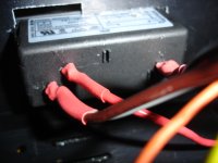
Would I measure the input AC voltage from the back of the power entry module

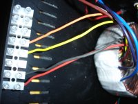
I have the secondaries separated by a terminal strip

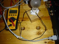
Testing the build with the bulb tester like this

Do I ground the black probe on the power entry module ground and use the red probe to test voltage on the (L) and (N) points?

I have the secondaries separated by a terminal strip

Testing the build with the bulb tester like this

Do I ground the black probe on the power entry module ground and use the red probe to test voltage on the (L) and (N) points?
Hi,
those one or two exposed terminals on the sides of the bulb holder are at mains voltage.
If you drop a metallic tool on one of them expect sparks.
Even a careless elbow while concentrating on something else could kill.
But as they are they are (dangerous) test points.
One side is direct to mains supply the other side is feed to the equipment being tested. If the equipment being tested is OK and consuming a very low current then the difference in voltage across the test bulb will be <<10Vac and more likely <1Vac. But, remember that they are both at mains voltage one at 120/240Vac and the other at ~119/239Vac.
Protect/insulate those terminals.
Health for all.
Thank you for your interest in my problem.
Dear Andrew T.
after your last answer were born in me doubts. To this I reply late because I wanted
with new measures to verify what I said.
Start over:
I have an old amply Scott A436 with the finals dead.I want replace only the final with 2 LM3875.
I bought two LM3875 by Peter Daniel and I have assembled.
The voltage standard of LM is 35volt. I have two 3-way speakers 40 watts into 8 ohms.
The power supply of Scott is composed of a transformer (rated values: 180 watt 100/120/220/240 volt 50/60 Hz
with power 3.5 amp fuse 100/120 V - 220/240 V 1.75 amp)
Following the party rettifricatrice and stabilized with two 6800microFarad electrolytic capacitors from 50 volts.
On Saturday, I disconnected the old end of Scott and I measured the voltage (half empty ---- say half because the
party still connected preamp)
Here the measured values:
Trasformatore---------ABC-------rettificatore/stabilizzatore----2 Capacitors
Vba 56.1 volts
Vbc 28.27v
Vac 28.24 v.
voltage across the capacitor and 40.3 volt 40.1v OK.
The Amply Scott worked with a voltage of 39 volts.
My problem is thus to lower the voltage from 40 volts and 35, preferably around the 32v because I do not want all
50 watts of LM
I have:
a resistance of 4.5 ohms 25 watts.
I think put out by two capacitors.
-------- Question No. 1 --------
Can I parallel two electrolytic capacitors because they have the same characteristics? Thus the output voltage levels even-
--------Question N° 2-------------
The PCB of LM has 9 holes :
OUT and OG -------- + and - speaker
IN and SG ---------- signal by preamply
PG+ ----------??????????? what?
PG- ----------???????????what?
the rest ok.
Thanks.
- Status
- This old topic is closed. If you want to reopen this topic, contact a moderator using the "Report Post" button.
- Home
- Amplifiers
- Chip Amps
- Power Supply Questions