Sir please sorry me because i am coming with very stupid question.
I am building lme49830 based amplifier with output device 2sk1058 and 2sj162.
In datasheet of both devices it is clear that both have pinout from left to right are gate souce and drain. Mosfet k1058 drain connected to +vcc and souce connected to dmm pin to measure quiescent current another mosfet sj162 source connected to dmm another pin and third last mosfet pin connected to -vee.
Now problem is when both gate disconnected sj162 heated abruptly with smoke. My design based on amp48 schematic and suppy voltage is too low for testing purpose 25-0-25 thnx in advance for suggesting me if i have done something wrong with devices
Short gate to source before connecting power.
With no gate drive, the stored charge in the G-S junction virtual capacitor will cause conduction.
You have to get rid of any residual charge (even FETs out of factory packing will have some stored charge) before doing what you're trying to do - not really sure what you're trying to discover with this experiment, though. It tells you nothing about the devices or your amplifier.
You may have already fried the MOSFETs.
Short gate to source before connecting power.
With no gate drive, the stored charge in the G-S junction virtual capacitor will cause conduction.
You have to get rid of any residual charge (even FETs out of factory packing will have some stored charge) before doing what you're trying to do - not really sure what you're trying to discover with this experiment, though. It tells you nothing about the devices or your amplifier.
You may have already fried the MOSFETs.
Thnx for reply
Not lets suppose mosfets got damaged.
Is it possible to connect any other device like bjt preferably 2n3055 without complementary i have only npn 10 pcs. Just for testing my board as a precaution. Because i don't want to destroy another pair of costly mosfet
Little old here but I have the same problem with the hybrid with 2sk1058 and 2sj162.
What helps for me is put a small cap 220p between gate and source of the 2sk1058 alone, and i get rid of all oscilations, did not try lowering the resistors
this problem I did now al some years..
It starts oscilating when go higher then 6 volts output with speaker connected (give some induction).
It is known about this problem because of differencies capacity between the fets. use as high capacity as needed, I have now use 47pF each fet, 220 pF is to high, limitting bandwith for hybride..
regards
kees
Hi Kees,
Sorry to react on an old thread, but I was surfing on the net for the famous 2SJ162/2SK1058 MOSFETs and the use of a small capacitor on the 2SK1058 to prevent oscillations.
In above post you are talking about 220pF (later 22pF) between the Source en Gate of the 2SK1058.
But in the schematics you draw this capacitor between Drain and Gate...
What is correct?
Usually a low capacity(10-22pF) between D and G is recommended, the higher capacity (220-390 pF) is used to compensate the different GS capacities of the p and n-channel MOSFETs or you can use different gate stopper resistors (each method has advantages and disadvantages).
BR
Günni
Usually a low capacity(10-22pF) between D and G is recommended, the higher capacity (220-390 pF) is used to compensate the different GS capacities of the p and n-channel MOSFETs or you can use different gate stopper resistors (each method has advantages and disadvantages).
BR
Günni
Thanks, Günni. Indeed, I didn't understand the 22pF was an additional capacitor.
The 220pF between Gate and Source I also found in Rod Elliott's design.
Usually a low capacity(10-22pF) between D and G is recommended, the higher capacity (220-390 pF) is used to compensate the different GS capacities of the p and n-channel MOSFETs or you can use different gate stopper resistors (each method has advantages and disadvantages).
BR
Günni
I have use 22pF, the mosfets get driven by een dc coupled tube EC99.
220 pf was a type error, I did use 22 pF
Using cap or gate resistor to get even respons of P and N channel, better is gate resistors because the lateral has low capacitance this is a good working method, if you do wel the 22pF
can even be removed, fase shifting occur when P and N are different als she always are, therefore I am busy with a circlotron, these do not oscillate, however sound like, circlotron sounds some more relaxed.
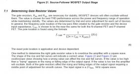
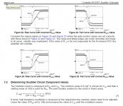
A way to get good respons is to use a square wave and adjust the gate resistors until the spike dissapear and the square gets just little as possible rounded corners, (20 Khz).
regards
Last edited:
Here it was hpw to do setup gate resistors for lowest HD and stability.
https://www.google.nl/url?sa=t&rct=...snaa045a.pdf&usg=AOvVaw38wCzbvsiTzp054l6JiKbC
regards
https://www.google.nl/url?sa=t&rct=...snaa045a.pdf&usg=AOvVaw38wCzbvsiTzp054l6JiKbC
regards
Attachments
Last edited:
- Status
- This old topic is closed. If you want to reopen this topic, contact a moderator using the "Report Post" button.
- Home
- Amplifiers
- Chip Amps
- LME49830 with 2SK1058/2SJ162 output stage


