Hi group, i would like some inputs about this:
i try to use their(ST) suggested bridged test circuit on a TDA2822m and i get very poor performance. It doesnt play bridged at all, one channel is barely getting anything out of it...if i ask the circuit to play a bit more it start to pop pop pop, and eventualy stop to work, i need to unpower it all.
There is no DC at the input, i have a 10uf decoupling cap (along with the 10k input resistor to gnd).
When i look at it it feels to me like a connection is missing, or a feedback from amp #1 to amp #2...
Each channels play OK in mono mode so it is not toasted.
This is meant to power up a white noise self unit for sleeping aid (dont ask further).
I got a bag of them for free and i thought i could use one in this project,
thanks for any inputs.
Attachments
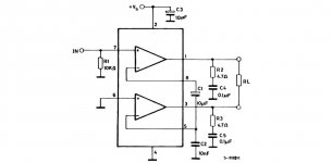

The circuit as shown on the data sheet does not work.
for mono bridge output:
You must put 100 uf on the output pins 1 &3 an connect them to the speaker for bridge output.
from pin 8 to pin 5 you should put a 10uf, +ve side on oin 8
from pin 5, 10uf to gound.
Pin 6 to ground
Input from pin 7
If you do not put the RC filter on the speakers, the cicuit will surely oscillate !
The circuit as shown on the data sheet does not work.
for mono bridge output:
You must put 100 uf on the output pins 1 &3 an connect them to the speaker for bridge output.
from pin 8 to pin 5 you should put a 10uf, +ve side on oin 8
from pin 5, 10uf to gound.
Pin 6 to ground
Input from pin 7
If you do not put the RC filter on the speakers, the cicuit will surely oscillate !
The bridge configuration according to the ST data sheets (schematic of post #1) worked fine for me, assembled on a socket board and 4.5VDC power supply.
How critical is the resistance value of the RC filter? I don't have 4.7 Ohm on hand, and I'd rather not parallel two 10 Ohm resistors that I do have on hand. Would 10 Ohm resistor in series with 0.1 microfarad cap be acceptable for the RC filter?
-Pete
yes it should work with 1-10 ohms
Thank you! Of course I'd like to understand at least somewhat what is involved in designing such filters if you would care to explain.
-Pete
Thank you! Of course I'd like to understand at least somewhat what is involved in designing such filters if you would care to explain.
-Pete
Without getting into a long explanation, the series RC network connected to the output of the amplifier aids in HF stability. The engineer who designed or tested the circuit chose the values that kept the amplifier stable with various loads that may be connected since he doesn't know the characteristics of the load customer will actually use. It is best to stay with the datasheet recommendation but you can certainly adjust the values for your use as long as stability is not lost.
Many of the new low power ICs have been designed to remain stable without the RC circuit on the output. Lots of the car stereo BTL chips have done away with them.
- Status
- This old topic is closed. If you want to reopen this topic, contact a moderator using the "Report Post" button.
- Home
- Amplifiers
- Chip Amps
- tda2822m problems...