A bit of a funny situation here.
I've been running a PIMETA headphone amp for .. a very long time. No problems at all, no noise, no DC offset to worry about.
Recently I thought I would check what would happen if I swapped my ground channel opamp - OPA134 with an OPA627 to match what's in the left/right channels. I found a couple and decided to try.
I couldn't spot difference - I mean, come on, they're almost the same thing anyway, plus this is the virtual ground channel and should theoretically matter less. Except that with the OPA627, things got weird. It was dead quiet without input signal (input not shorted but not connected either). Same thing happens with the OPA134. With signal though, it got noisy at higher volumes. "Noisy source" you'd think, but no - with the OPA134, the noise from the source (PC sound card) can be felt only at the highest pot position. And then - when you turn off the power with the OPA627, a high-pitched whine shows up, like turning off an old TV set. With the OPA134, a very slight "thump" can be felt, since the capacitor bank of my PIMETA is after the power switch and they take a little to drop charge after you flip the switch off.
So, apparently the those OPA627 i tried weren't stable in this ground channel, in my amp. Funny though, I wouldn't expect that to happen.
EDIT: Oh, I know OPA637 wouldn't be stable in unity gain, but the ones I've got clearly say 627 on them, I double-checked")
I've been running a PIMETA headphone amp for .. a very long time. No problems at all, no noise, no DC offset to worry about.
Recently I thought I would check what would happen if I swapped my ground channel opamp - OPA134 with an OPA627 to match what's in the left/right channels. I found a couple and decided to try.
I couldn't spot difference - I mean, come on, they're almost the same thing anyway, plus this is the virtual ground channel and should theoretically matter less. Except that with the OPA627, things got weird. It was dead quiet without input signal (input not shorted but not connected either). Same thing happens with the OPA134. With signal though, it got noisy at higher volumes. "Noisy source" you'd think, but no - with the OPA134, the noise from the source (PC sound card) can be felt only at the highest pot position. And then - when you turn off the power with the OPA627, a high-pitched whine shows up, like turning off an old TV set. With the OPA134, a very slight "thump" can be felt, since the capacitor bank of my PIMETA is after the power switch and they take a little to drop charge after you flip the switch off.
So, apparently the those OPA627 i tried weren't stable in this ground channel, in my amp. Funny though, I wouldn't expect that to happen.
EDIT: Oh, I know OPA637 wouldn't be stable in unity gain, but the ones I've got clearly say 627 on them, I double-checked
Last edited:
but most reasonable and right thinking designers would expect a straight swap of opamps to require sorting!I wouldn't expect that to happen.
Well, 627 has got 1/2 the noise and double the slew rate. The first parameter isn't a problem while the speed could potentially be. It's just that other people have used the same board and chips without issues, so I thought I'd share the story.
I'd add some local bypasses but for that I need to disassemble the amp. I'm sure I'll break something if I do though, so it's more likely I'll see how this goes on the next headphone amp I build. Or ... I could directly bypass it on the pins ... hmmm ... Ceramic NP0 should be fine, right?
I'd add some local bypasses but for that I need to disassemble the amp. I'm sure I'll break something if I do though, so it's more likely I'll see how this goes on the next headphone amp I build. Or ... I could directly bypass it on the pins ... hmmm ...
Ceramic NP0 should be fine, right?are they the only differences?627 has got 1/2 the noise and double the slew rate.
What is slew rate?
It's the amps ability to change voltage with time.
If the amp has any capacitance to charge then a doubled slew rate ability implies a doubled current demand.
A doubled current demand requires decoupling to suit. See what the manufacturer recommends. POUR OVER the datasheet.
Two things could be the culprit here:
Missing local bypass caps for the opamp - they're always good to have, but in this case it's not driving a load directly, the buffer is.
However, the BUF634 that's used must be in wide bandwidth mode with fast opamps and the OPA627 is quite faster than the OPA134. IIRC my buffers have a bandwidth limiting resistor, which keeps it pretty high, but not at maximum.
Now that I remember that, I bet it's a combination of both.
Without proper decoupling OPA627 I would not even bother to try it as you know beforehand it won't perform as it should. It is one of the most sensitive opamps for decoupling (with or without another chip driving the load). I really do not understand why people use high speed high bandwidth parts without even reading the datasheet or adhering to the basic requirements. To me these cases sound like one is complaining about the performance of his diesel car after having it filled up with petrol Indeed opamps can be a lot of fun when used right.
A 10 to 47 uF good quality low ESR electrolytic cap from + to GND, again one of those from - to GND and finally one 10 nF to 1 uF film cap ( I often use 10 or 100 nF Wima MKT 5 mm pitch as they fit perfectly) from + to - directly on the pins will do. The latter is quite important. Then check again how it works.
Indeed opamps can be a lot of fun when used right.A 10 to 47 uF good quality low ESR electrolytic cap from + to GND, again one of those from - to GND and finally one 10 nF to 1 uF film cap ( I often use 10 or 100 nF Wima MKT 5 mm pitch as they fit perfectly) from + to - directly on the pins will do. The latter is quite important. Then check again how it works.
Last edited:
The Pimeta’s "3-channel" topology is fundamentally flawed - most technical reasons given for it are simply not true or can be bettered by proper layout
"active supply splitter" can be useful when wanting to use single V supply - the single active gnd should be used for input, feedback and load gnd
but "3-channel" puts the gnd “buffer” amp in series with the load - with the input and feedback grounds separated from the load gnd - this means all of the error of the "output gnd" buffer is in series with the headphones - giving distortion and "output gnd" impedance crosstalk that is worse than with a good "passive" gnd of heavy conductor with signal input gnd, feedback gnd "star" connected with the load common ground pin of the TRS connector
A "active gnd" showing star at output - can better "3-channel" performance:
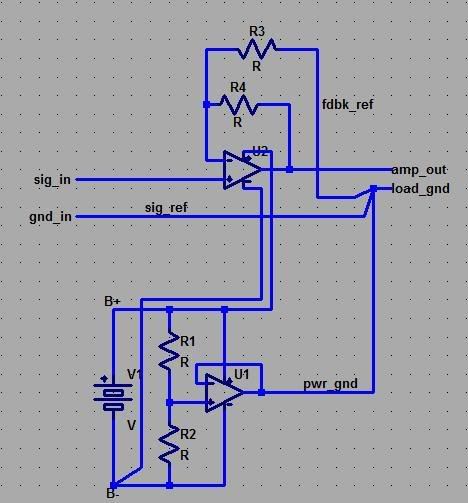
particularly with the near 2000 uF of supply C of the Pimeta on the "input gnd" adding a buffered "output gnd" is a waste - just calculate and add a series R for the tle2426 that keeps it from going into current limit with your cans and the supply C with 20 Hz full scale signal - this gives a AC gnd at audio frequencies, cuts AC current draw in half vs active or 3 channel gnd
without a oscilloscope you really can't tell what's causing your observed problems - but I wouldn’t' give any weight to the noises you get after the power is removed - details of drop out behavior as the op amp supply V drops past the minimum data sheet spec isn't a good reason to choose audio op amps - if its a big problem then add a output relay or power supply crowbar - or just unplug the phones 1st
"active supply splitter" can be useful when wanting to use single V supply - the single active gnd should be used for input, feedback and load gnd
but "3-channel" puts the gnd “buffer” amp in series with the load - with the input and feedback grounds separated from the load gnd - this means all of the error of the "output gnd" buffer is in series with the headphones - giving distortion and "output gnd" impedance crosstalk that is worse than with a good "passive" gnd of heavy conductor with signal input gnd, feedback gnd "star" connected with the load common ground pin of the TRS connector
A "active gnd" showing star at output - can better "3-channel" performance:
particularly with the near 2000 uF of supply C of the Pimeta on the "input gnd" adding a buffered "output gnd" is a waste - just calculate and add a series R for the tle2426 that keeps it from going into current limit with your cans and the supply C with 20 Hz full scale signal - this gives a AC gnd at audio frequencies, cuts AC current draw in half vs active or 3 channel gnd
without a oscilloscope you really can't tell what's causing your observed problems - but I wouldn’t' give any weight to the noises you get after the power is removed - details of drop out behavior as the op amp supply V drops past the minimum data sheet spec isn't a good reason to choose audio op amps - if its a big problem then add a output relay or power supply crowbar - or just unplug the phones 1st
Last edited:
dual supply is good too with similar attention to layout
if you want to go portable I'd just use the middle of the battery stack but the head-fi crowd worry about unequal discharge if you leave power on accidentally - a supply splitter can be "safer" in that scenario or is used with a single "9 V" battery supply
if you want to go portable I'd just use the middle of the battery stack but the head-fi crowd worry about unequal discharge if you leave power on accidentally - a supply splitter can be "safer" in that scenario or is used with a single "9 V" battery supply
are they the only differences?
What is slew rate?
It's the amps ability to change voltage with time.
If the amp has any capacitance to charge then a doubled slew rate ability implies a doubled current demand.
A doubled current demand requires decoupling to suit. See what the manufacturer recommends. POUR OVER the datasheet.
PORE over the datasheet? I sometimes like to pour one or two while I pore. But I don't usually pour OVER the datasheet, because sometimes I spill a bit, which would be even worse if the datasheet were on my monitor.
(Sorry AndrewT. Couldn't stop myself.)
Cheers,
Tom
- Status
- This old topic is closed. If you want to reopen this topic, contact a moderator using the "Report Post" button.
- Home
- Amplifiers
- Chip Amps
- Opamps, aren't they a lot of fun sometimes?