Hi,
I'm a newbie so bear with with my (naive) attempts to describe my findings.
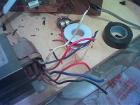
i have this working transformer scavenged from a junked JVC receiver (which is spec'd at 210watts / 270VA power consumption from the chassis).
I hooked up the primaries to the mains and tried to measure the voltages across the secondaries (2 red, 2 blue, a white and a black)
the black seems to be at the lowest potential so i assume it is ground.
with respect to this, the other AC voltages are
the 2 reds measure at 35V each
one of the bue measures at 15V and the other at 10V
the white measures at 5V.
Q1. am i right in assuming that the 2 reds are the leads to use. If so, is this voltage too high. I read through this forum and a few sites on the www and people seem to indicate that 20 or so V is the max suggested. The product sheet for my chip (lm3875T) however tells me on page 3 that the recommended input voltage should be between 20 to 84V. from the same product sheet, i do also notice from a graph of clipping vs. supply voltage that there is less tolerance (headroom?) at higher voltages.
Q2. if i must operate at 20+V, is there a way i could perhaps take down the voltage, using a load resistor, or some kind of shunt mechanism.
Q3. alternatively, can i divide each secondary of 35V to 2 lines so i can essentially run 2 channels off each line,
thanks in advance
I'm a newbie so bear with with my (naive) attempts to describe my findings.
i have this working transformer scavenged from a junked JVC receiver (which is spec'd at 210watts / 270VA power consumption from the chassis).
I hooked up the primaries to the mains and tried to measure the voltages across the secondaries (2 red, 2 blue, a white and a black)
the black seems to be at the lowest potential so i assume it is ground.
with respect to this, the other AC voltages are
the 2 reds measure at 35V each
one of the bue measures at 15V and the other at 10V
the white measures at 5V.
Q1. am i right in assuming that the 2 reds are the leads to use. If so, is this voltage too high. I read through this forum and a few sites on the www and people seem to indicate that 20 or so V is the max suggested. The product sheet for my chip (lm3875T) however tells me on page 3 that the recommended input voltage should be between 20 to 84V. from the same product sheet, i do also notice from a graph of clipping vs. supply voltage that there is less tolerance (headroom?) at higher voltages.
Q2. if i must operate at 20+V, is there a way i could perhaps take down the voltage, using a load resistor, or some kind of shunt mechanism.
Q3. alternatively, can i divide each secondary of 35V to 2 lines so i can essentially run 2 channels off each line,
thanks in advance
Attachments
interesting, .....
so this could actually provide me with a means to observe gainclone performance with varying operating voltage
i'm not dead in the water after all
could someone post a simple and suitable shunt regulator schematic. i googled upon this and came up with some very elaborate schemes, probably overkill for this purpose
thanks, vin
thanks, mucho useful information and i see several simple circuits that might work. however, more questions:
do i need to build 2 regulators for each 35V output or just one
.... it seems that shunt regulators are classified both by the voltage they can provide as well as the current capacity.
considering that my PS is rated at 210W / 270VA, i would roughly say that the max current at the secondary would be roughly 7A at 35V. should i design for this current, or can i safely assume that the gainclone will not draw this much current (if so, how much will it draw - sorry, the specshhet only talks about output or bias current)
thanks
- Status
- This old topic is closed. If you want to reopen this topic, contact a moderator using the "Report Post" button.