
I saw this in some other thread. Are you double posting?
There too, there was no link to Carlos' schematic.
And no schematic nor trace layout for this proposal.
How can you expect any sensible comment?
There too, there was no link to Carlos' schematic.
And no schematic nor trace layout for this proposal.
How can you expect any sensible comment?
I saw this in some other thread. Are you double posting?
There too, there was no link to Carlos' schematic.
And no schematic nor trace layout for this proposal.
How can you expect any sensible comment?
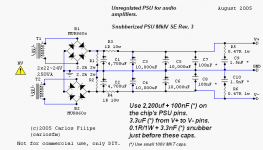
Hi AndrewT,
This is made by me only. I am not posting it twice in this forum.
And sorry🙁 for not attaching the original schematic.
Here it is.
Made on Express PCB
waiting for comments😀😀
Attachments
Last edited:
waiting for comments😀😀
More of a question really - I can't really see what the point of the 1.5nF and 0R47 snubber networks is. The fact that the 0.47ohm resistors are 1W rated seems to suggest there's going to be a fair amount of RF to soak up yet the 1.5nF is spec'd as an MKT. As far as I'm aware these have significant series inductance which will successfully block any RF from reaching the resistor.
If you're serious about soaking up RF above 50MHz on the supply, you'd need to use, say, a bunch of WIMA FKP02 100pF polypropylenes in parallel - this particular value has an SRF close to 200MHz. Or alternatively use SMT C0Gs.
Oh, and I'd split the 1R 10W resistor into two 0.47s and use the first where the 1R is now and the second between the two 10,000uFs. I think two RC filtration stages in series will be quite a bit better than one.
Hi abraxalito,🙂
If i have understood it correctly i have to use 2 x 0.47/1watt accros the each 10000 caps instead of single 1e/10w used before two caps.
As i have mentioned earlier that the schematic is solely done by Carlos FM & the result is posted on Nukk and vikash chauhan's website.
Hence i have just prepared a simple DIY single sided board to use it with my chipamp based on schemetic by carlos.. I just want to know that is the layout is correct or not.
Thanks🙂🙂
Hi abraxalito,🙂
Hiya😎
If i have understood it correctly i have to use 2 x 0.47/1watt accros the each 10000 caps instead of single 1e/10w used before two caps.
No, you didn't understand me correctly, but as you don't want comments on the schematic but only on the layout, I'll shut up now😛 For me though, its important to get the schematic optimised before considering the layout.😀
Hi abraxalito,🙂
If i have understood it correctly i have to use 2 x 0.47/1watt accros the each 10000 caps instead of single 1e/10w used before two caps.
As i have mentioned earlier that the schematic is solely done by Carlos FM & the result is posted on Nukk and vikash chauhan's website.
Hence i have just prepared a simple DIY single sided board to use it with my chipamp based on schemetic by carlos.. I just want to know that is the layout is correct or not.
Thanks🙂🙂
I think what abrax is telling you is that the circuit can be made to perform much better by just a few simple changes (and I agree). It's clear from the circuit what whoever drew it wanted to do but he/she didn't get it quite right.
So it's your choice whether you want to discuss that, and learn something in the process or stay with how it is.
jd
Hiya😎
No, you didn't understand me correctly, but as you don't want comments on the schematic but only on the layout, I'll shut up now😛 For me though, its important to get the schematic optimised before considering the layout.😀
Hi abraxalito

🙂 Please don't take me wrong. i've never think about it.

Your valuable suggestion are welcome & the purpose of posting the layout in this forum is to get suggestion & guidance from persons who have deep knowledge about the same. kindly suggest the required improvements.
Hi abraxalito
🙂 Please don't take me wrong. i've never think about it.
Jan's quite right - not everyone wants to learn, some prefer just to copy a schematic they find from somebody else. Its not a bad thing if all you want to do is copy - but then I won't waste time trying to educate you😀
As I mentioned earlier, it would be better to have two stages of RC filtering than merely one. At present your Rs are the 1R/10W resistors prior to the first 10,000uF caps. I'm suggesting that you split the 1R notionally into two half-ohm resistors (5W each) and put the first one in place of the 1R you have now. The second one goes in the +ve line between C3 and C5. Ditto for the negative side.Your valuable suggestion are welcome & the purpose of posting the layout in this forum is to get suggestion & guidance from persons who have deep knowledge about the same. kindly suggest the required improvements.
Also the snubber part of the circuit doesn't look so well thought out (though I will point out here I have little experience with snubbers). It looks to be to absorb high RF frequencies (I deduce this from the lowish capacitor value, 1.5nF), but won't be likely to do that unless the right capacitor is specified and its layed out correctly. I will have a look at your layout later and make some suggestions.
It might be useful to reference the original thread on this design...
http://www.diyaudio.com/forums/chip-amps/43423-high-cap-unregulated-psu-chipamps.html
http://www.diyaudio.com/forums/chip-amps/43423-high-cap-unregulated-psu-chipamps.html
It might be useful to reference the original thread on this design...
http://www.diyaudio.com/forums/chip-amps/43423-high-cap-unregulated-psu-chipamps.html
Great link! The thing that made me LOL was that he first complains about the high inductance of large caps, that he 'solves' this with an extra cap and snubber and then - get this - says he connected the extra cap and snubber with wires and alligator clips and heard an improvement. The gems you can read online! 😉
jd
Great link! The thing that made me LOL was that he first complains about the high inductance of large caps, that he 'solves' this with an extra cap and snubber and then - get this - says he connected the extra cap and snubber with wires and alligator clips and heard an improvement. The gems you can read online! 😉
Yes, thanks for the heads up on that little bit of history. I found it as entertaining as Jan at first but gave up after about 250 posts.
So it seems based on that, that the snubber isn't supposed to be dealing with RF on the supply, its supposed to compensate for the allegedly higher inductance of bigger reservoir caps. Yeah, right, as Jan points out.
What's missing there is seeing the schematic and layout of the amp the supply is feeding (via those croc clips). Also by post 250 the snubber capacitor value was still 100n yet in the one on this thread its somehow got down as low as 1.5nF. Carlos originally said that 'lower was better' but then didn't feel that lower than 100n would make any improvement. But then he also said that it needed to be after the big caps or its effectiveness would be lost, but said perhaps it could be straight after the rectifiers.
So all in all not a lot of light shed up to post 250. Has anyone the interest to read to the end in order to find out what the story is behind 1.5nF? I can sort of guess at the 'reasoning' - this supply also has 20,000uF whereas the original one has 10,000uF so perhaps the new lower snubber value compensates for that extra inductance brought about by adding 10,000uF?😀
Jan, don't be such a scientist!
Sorry... (And I mean that. Old habits die hard).
jd
I thought snubbers were supposed to cancel resonances caused by inductive/capacitive elements, in this case the transformer and reservoir caps. You can't cancel the actual inductance of the reservoir caps themselves, that's ridiculous.
Even if we accept that CarlosFM's snubber works (and it's a big if since he's not presented any hard evidence to support his claims other than what he hears which, as we all know, is not all that reliable on a scientific basis), surely the snubber values he suggests will only be valid for the particular make of transformer and electrolytic reservoir caps he uses since they depend on the transformer's leakage inductance and capacitance and the caps' inductance and ESR.
If you try it on your power supply you may need to change the values.
Last edited:
I thought snubbers were supposed to cancel resonances caused by inductive/capacitive elements, in this case the transformer and reservoir caps. You can't cancel the actual inductance of the reservoir caps themselves, that's ridiculous.
Even if we accept that CarlosFM's snubber works (and it's a big if since he's not presented any hard evidence to support his claims other than what he hears which, as we all know, is not all that reliable on a scientific basis), surely the snubber values he suggests will only be valid for the particular make of transformer and electrolytic reservoir caps he uses since they depend on the transformer's leakage inductance and capacitance and the caps' inductance and ESR.
If you try it on your power supply you may need to change the values.
Theres a thread floating around on how to calculate snubbers, but Im sure it was solely dependant on the transformers leakage inductance, or did I miss something?
Is It right??
Engineering, like life, isn't so black and white as 'right' and 'wrong'. Its more a question of optimising within certain constraints. So no, its not optimum yet because you haven't adopted a star ground. So even though you're filtering the noise on the + and - rails, you're at the same time introducing noise on your ground by bussing it along various caps. To get a really nice quiet supply, the grounds to the 10,000uF caps need to have their own unique path back to a central star point. Then the output ground is another lead out from the star. Make the area between the 2k2 resistors into your star and all the other ground connections then lead out direct from this.
Apart from this, it looks fine as regards placement😀
I thought snubbers were supposed to cancel resonances caused by inductive/capacitive elements, in this case the transformer and reservoir caps.
There are different schools of thought on this. Some (as jackinnj) on that thread say they're for damping down rectifier turn-off spikes. Others (such as yourself) maintain they're for dealing with transformer/capacitor resonances. My own view is slightly different: that they may have value in reducing (by dissipating) the RF on the supply.
You can't cancel the actual inductance of the reservoir caps themselves, that's ridiculous.
I think in theory it must be possible to cancel out an inductance with a parallel capacitance, but I agree that in practice its not really going to work as the inductance isn't too predictable and comes with its own series resistance. But I didn't hear Carlos saying he was cancelling inductance, rather reducing it. Myself I question the whole thinking behind Carlos' damping factor arguments. A chipamp's DF is mainly determined by its NFB and OL output impedance, not really the supply.
Even if we accept that CarlosFM's snubber works (and it's a big if since he's not presented any hard evidence to support his claims other than what he hears which, as we all know, is not all that reliable on a scientific basis), surely the snubber values he suggests will only be valid for the particular make of transformer and electrolytic reservoir caps he uses since they depend on the transformer's leakage inductance and capacitance and the caps' inductance and ESR.
No, because he's not trying to cancel out (or reduce) transformer resonances. To me its scientific to accept that Carlos heard differences, but those differences can be contextual. My working hypothesis is that his snubbers did affect the RF going from the PSU onto his amp PCB, but because his amp PCB decoupling wasn't optimal the different RF levels made differences to the sound. So, far better to fix the amp decoupling first (doesn't need additional components, just different wiring topology), then see if the snubbers make any further improvement. Because I didn't see which amp he was listening to (schematic and layout) then its really just an educated guess. If it turns out his amp was optimally decoupled, then its back to the drawing board for me😀
If you try it on your power supply you may need to change the values.
Yep, I agree there.😀
http://www.hagtech.com/pdf/snubber.pdf may be of interest.
Also national semiconductor's approach to PSU:
http://www.national.com/an/AN/AN-1849.pdf
Also national semiconductor's approach to PSU:
http://www.national.com/an/AN/AN-1849.pdf
- Status
- Not open for further replies.
- Home
- Amplifiers
- Chip Amps
- Hi-Cap PS By Carlos FM