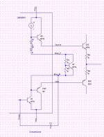
Here are some ideas for playing with LME49810. The conventional compensation cap is connected between Comp and BiasM pins. This is shown in the left most figure. Output NPN/PNP is connected to Source/Sink pins. We can omitt the LME49810 internal buffer as shown in the second figure. Output PNP is directly connected to the collector of the VAS, BiasM pin. I have not tried this.
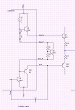
We can connect the comp cap across Comp and Sink pins as shown in the third figure. I did this without seeing major issue. Need more test for performance evaluation.
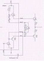
We can also insert a resistor between Bias_M and Sink pins to bootstrap VAS collector. This is from D. Self's Amplifier Handbook Fig 5.4 f. I have not tested it yet.
Any comment?
We can connect the comp cap across Comp and Sink pins as shown in the third figure. I did this without seeing major issue. Need more test for performance evaluation.
We can also insert a resistor between Bias_M and Sink pins to bootstrap VAS collector. This is from D. Self's Amplifier Handbook Fig 5.4 f. I have not tested it yet.
Any comment?
Attachments
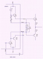
With the buffer omitted you essentially end up with an LME49811.
Note that the compensation scheme changes depending on the configuration. I'd definitely be careful and preferably run an open loop gain/phase measurement before committing to a final circuit.
Good thoughts, though.
~Tom
Note that the compensation scheme changes depending on the configuration. I'd definitely be careful and preferably run an open loop gain/phase measurement before committing to a final circuit.
Good thoughts, though.
~Tom
With the buffer omitted you essentially end up with an LME49811.
Note that the compensation scheme changes depending on the configuration. I'd definitely be careful and preferably run an open loop gain/phase measurement before committing to a final circuit.
Good thoughts, though.
~Tom
Hi Tom,
Thanks for your advice. How do you do open loop measurement? I tried the scheme given in Self's amplifier handbook.
Panson
open-loop gain and phase of LME49810
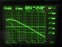
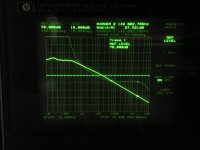
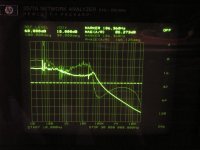
I used HP3577A to measure the open-loop gain of 49810. The chip was in inverting mode. INPUT R of 3577 was connected to the inverting input pin. INPUT A of 3577 was connected to the output. Note the dynamic range of 3577 is 100 dB. It limits the accuracy of low frequency measurement where the open-loop gain is over 100 dB.
The left picture shows the measured data for 10 pF cap connected across Comp and Bias_M pins. The gain at 10 Hz is about 108 dB instead of 120 dB. This is due to dynamic range limitation of 3577. What is more important is the crossover frequency at which the loop-gain is 0 dB. The feedback resistor network (240R, 5k6) gain is - 27.7 dB. Loop-gain 0 dB is equivalent to open-loop gain 27.7 dB. The corresponding phase shift is 109.5 degree. Hence, the phase margin is 70.5 degree. The crossover frequency is 2.29 MHz.
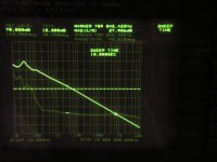
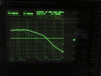
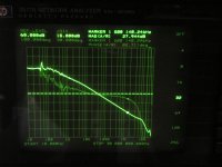
The middle picture shows the open-loop gain for a comp. cap of 32 pF. The phase margin is slightly increased to 86.2 degree. The crossover frequency is reduced to 709 kHz.
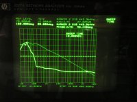
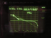
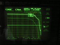
The third picture is the open-loop gain with a 10 pF connected across Comp and Sink pins. The phase margin is 86.6 degree. Crossover frequency is 2.22 MHz. Compared to case 1 (10 pF), we have a better phase margin and similar BW.
I used HP3577A to measure the open-loop gain of 49810. The chip was in inverting mode. INPUT R of 3577 was connected to the inverting input pin. INPUT A of 3577 was connected to the output. Note the dynamic range of 3577 is 100 dB. It limits the accuracy of low frequency measurement where the open-loop gain is over 100 dB.
The left picture shows the measured data for 10 pF cap connected across Comp and Bias_M pins. The gain at 10 Hz is about 108 dB instead of 120 dB. This is due to dynamic range limitation of 3577. What is more important is the crossover frequency at which the loop-gain is 0 dB. The feedback resistor network (240R, 5k6) gain is - 27.7 dB. Loop-gain 0 dB is equivalent to open-loop gain 27.7 dB. The corresponding phase shift is 109.5 degree. Hence, the phase margin is 70.5 degree. The crossover frequency is 2.29 MHz.
The middle picture shows the open-loop gain for a comp. cap of 32 pF. The phase margin is slightly increased to 86.2 degree. The crossover frequency is reduced to 709 kHz.
The third picture is the open-loop gain with a 10 pF connected across Comp and Sink pins. The phase margin is 86.6 degree. Crossover frequency is 2.22 MHz. Compared to case 1 (10 pF), we have a better phase margin and similar BW.
Attachments
Last edited:
open-loop gain of LME49810 with two-pole compensation
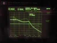
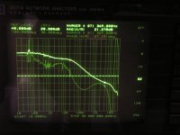
The two-pole compensation consists of 10 p, 5k6 and 56 p. The measured open-loop gain is shown in the left picture. We can clearly see that the gain in high frequencies is increased substantially. Compared to single-pole, gain at 20 kHz is increased from ~65 dB to 85 dB. Note the measurement was the chip alone.
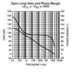
Middle picture is single-pole (10 pF) open-loop gain for up to 10 MHz. I show it here for comparison with the open-loop gain given in the data sheet.
The two-pole compensation consists of 10 p, 5k6 and 56 p. The measured open-loop gain is shown in the left picture. We can clearly see that the gain in high frequencies is increased substantially. Compared to single-pole, gain at 20 kHz is increased from ~65 dB to 85 dB. Note the measurement was the chip alone.
Middle picture is single-pole (10 pF) open-loop gain for up to 10 MHz. I show it here for comparison with the open-loop gain given in the data sheet.
Attachments
49810 open-loop gain
I fine tuned the measurement. Better result is obtained. The open-loop gain for single-pole (10 pF) is shown in the left picture. The middle is two-pole (10 pF, 5k6 and 56 pF). The right one is another two-pole (10 pF, 5k6 and 151 pF). These three are the gain of 49810 alone.
I fine tuned the measurement. Better result is obtained. The open-loop gain for single-pole (10 pF) is shown in the left picture. The middle is two-pole (10 pF, 5k6 and 56 pF). The right one is another two-pole (10 pF, 5k6 and 151 pF). These three are the gain of 49810 alone.
Attachments
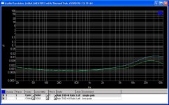
LME49810 with ThermalTrak open-loop gain
With two-pair ThermalTrak connected as output stage (MJE15030/32 driver), the open-loop gain was measured. No dummy load was connected.
Left: single-pole with 10 pF comp. cap
Middle: freq response of single-pole with 10 pF com. cap (inverting)
Right: two-pole with 10pF, 5k6 and 51 pF
The addition of output stage introduces zeros and poles in very high freq region (> 5 MHz). As show, the two-pole case has higher gain in the audio band. For instance, it has over 80 dB at 20 kHz whereas single-pole case is about 65 dB. The two-pole compensated amp should result in lower THD in that band. It will be verified next.
Attachments
Last edited:
Hello Panson!
Did you ever get some results with the tpc? How about stability?
Did you ever try bootstraping as shown in pic 4?
How about bootstraping from the PA output?
BR,
Dag
Hi Dag,
Yes, I made a 49811 amp with TPC. No oscillation was observed.
Here is THD comparison for SPC and TPC.
Bootstrapping has not been evaluated.

Panson
Attachments
and this was preceded by at least two other threads discussing this particular bootstrap VAS drive topology.some people (like the latest Dx amp) use bootstrap + current source.
- Status
- This old topic is closed. If you want to reopen this topic, contact a moderator using the "Report Post" button.
- Home
- Amplifiers
- Chip Amps
- More funs with LME49810