so the rca1 ground goes to rca2 ground(with a wire_A), and then i connect the middle of wire_A with the star point. Then i connect pot's ground1 with pcb1 signal-in-ground(wire_B),pot's ground2 with pcb2 signal-in-ground(wire_c), and i connect the middle of wire_B with the star and the middle of wire_C with the star?
what is the difference now?rca ground are coonnected with the star, but also pcb sigal-in-ground are connected with the star. If rca ground has noice(because rca cable is an antenna) that noise will also go to the pcb signal-in-groun from the route: rca-ground->star point->pcb signal-in-ground..
Am i missing something?
Last edited:
so the rca1 ground goes to rca2 ground(with a wire_A)
I have no idea what rca1 and rca2 are referring to here.
and then i connect the middle of wire_A with the star point. Then i connect pot's ground1 with pcb1 signal-in-ground(wire_B),pot's ground2 with pcb2 signal-in-ground(wire_c), and i connect the middle of wire_B with the star and the middle of wire_C with the star?
Likewise no clue as to how a pot can have grounds 1 and 2, nor which pcb1 and pcb2 are. Please clarify.
a female rca socket has two 'pins'.one for the signal and one for the ground. I mean rca socket' ground pin. i have this rca socket: http://www.traderscity.com/board/userpix17/14288-chassis-mount-rca-jack-socket-1.jpg.
there also two types of pot:
3 pin:http://img.alibaba.com/photo/292782...ereo-Potentiometer-Pots-Shaft-S-15mm.summ.jpg
and 6 pin:http://myweb.tiscali.co.uk/nuukspot/decdun/gc/pot1.jpg
The 6 pin has 2 grounds!
there also two types of pot:
3 pin:http://img.alibaba.com/photo/292782...ereo-Potentiometer-Pots-Shaft-S-15mm.summ.jpg
and 6 pin:http://myweb.tiscali.co.uk/nuukspot/decdun/gc/pot1.jpg
The 6 pin has 2 grounds!
can you correct this shcematic acocording to what you are saying?
http://img718.imageshack.us/img718/8347/ok2h.jpg
its the topology of "understanding star ground" thread.[post5]
http://www.diyaudio.com/forums/chip-amps/115698-understanding-star-grounding.html
http://img718.imageshack.us/img718/8347/ok2h.jpg
its the topology of "understanding star ground" thread.[post5]
http://www.diyaudio.com/forums/chip-amps/115698-understanding-star-grounding.html
Last edited:
a female rca socket has two 'pins'.one for the signal and one for the ground. I mean rca socket' ground pin.
Still confused. You can't mean that rca1 = rca socket ground pin and rca2 = rca socket signal pin because you're suggesting to short rca1 and rca2 together. So are you meaning left channel rca by 'rca1' and right channel rca by 'rca2' ?
two types of pot:
3 pin:http://img.alibaba.com/photo/292782...ereo-Potentiometer-Pots-Shaft-S-15mm.summ.jpg
and 6 pin:http://myweb.tiscali.co.uk/nuukspot/decdun/gc/pot1.jpg
The 6 pin has 2 grounds!
Yeah, those pics show stereo pots. So one group of 3 pins is for left, the other for right. You need to connect the left channel pot ground only to the left channel pcb, and the right channel pot ground only to the right channel pcb.
can you correct this shcematic acocording to what you are saying?
No, it looks like that website is blocked by the great firewall of China and I don't have my VPN set up on this machine.
look me last post if you can.
yeah rca1 is the left channel(and has ground1) and rca2(which has ground2) is the right! you said to connect ground1 with ground2 and then use a wire to the star ground.
according to post4 of "undersanding star grounding" if you trie to connect pot ground to pcb signal-in-ground for both the pots you have a ground loop..
Last edited:

according to post4 of "undersanding star grounding" if you trie to connect pot ground to pcb signal-in-ground for both the pots you have a ground loop..
Some ground loops are unavoidable in a stereo amplifier. Both left and right channels share the same ground at the source, then there are two cables run in parallel (your left and right channels) which are then connected together at the amp end. The left-gnd and right-gnd are going to be in a loop, its unavoidable unless we go for full mono-block construction with separate supplies for left and right. Ground loops are only a worry if there's something pushing current around in them - in these cases its fairly insignificant.
If you're wanting the ultimate sound quality (which is what I'm working on) then balanced interconnections are the only way to go. The professionals have been working this way for years, seems domestic hifi is stuck in the dark ages

this is the schematic:
Yep, in my estimation that's wrong, it doesn't follow my recommendations over the rca grounds for a start. But there are others who disagree - so follow whoever you trust the most
this is the rca cable that i am using: http://www.e-shop.gr/show_per.phtml?id=PER.750723http://www.e-shop.gr/show_per.phtml?id=PER.750723.
I think that has only one ground cable, that splits on two in the end. So a ground loop between amplifier and the source can't occur..is that correct?
I think that has only one ground cable, that splits on two in the end. So a ground loop between amplifier and the source can't occur..is that correct?
Last edited:
I think that has only one ground cable, that splits on two in the end. So a ground loop between amplifier and the source can't occur..is that correct?
No, not correct - as soon as both the white and red rcas are connected to your amp, there's a ground loop.
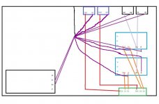
Here's my suggested topology, wiggly hand drawn lines not to be taken too literally...
Attachments
- Status
- This old topic is closed. If you want to reopen this topic, contact a moderator using the "Report Post" button.
- Home
- Amplifiers
- Chip Amps
- Lm3886 grounding made easy(?)