On the 19th June last year I said I was going to have a go at building a Gainclone.
Well, a year later and I have bought the boards from the far east and bought my own bits and loaded it all up.
It works well, is quiet and was a bit of a pleasant surprise in all sound departments.
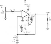
I want to remove two components which don't appear on the attached gainclone schematic I found recently.
Can I remove R1 and C5 and replace them with a wire link ?
Will it still be stable and safe plus is there any sound quality to be gained by doing so ?
Many thanks for all the help last year and sorry for the delay
Andrew.
Well, a year later and I have bought the boards from the far east and bought my own bits and loaded it all up.
It works well, is quiet and was a bit of a pleasant surprise in all sound departments.
I want to remove two components which don't appear on the attached gainclone schematic I found recently.
Can I remove R1 and C5 and replace them with a wire link ?
Will it still be stable and safe plus is there any sound quality to be gained by doing so ?
Many thanks for all the help last year and sorry for the delay
Andrew.
Attachments
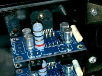
I can't find R1.
The datasheet details the purpose of C5. (no it's Cs I see), where is C5?
I do not see any of the National "optional" components. Tread carefully, this chipamp may blow itself up and/or take out your speakers, if even mildly abused.
The PCB has C5 and R1.
place them on the schematic.
What is that high power resistor standing upright?
I get the impression that your kit supplier has included the "optional" components. If so then keep all of them and add the few more that are still missing.
Last edited:
my guess is that R1 (as i see it on the pcb photo) is on the output. I can not be 100% sure.
if you are NOT putting these amplifiers in parallel then you should be able to take out R1 and bridge it. But you need to be 100% sure.
I cannot comment on C5 without seeing the schematic.
if you are NOT putting these amplifiers in parallel then you should be able to take out R1 and bridge it. But you need to be 100% sure.
I cannot comment on C5 without seeing the schematic.
Thanks for the replies.
Andrew T : The confusion is created by me - apologies.
The schema is not the one relating to the photo of my baords.
I recently found this drawing and noticed that the large resistor R1 ( 1R 5 watt ) on the output is not in the drawing and the capacitor C5 ( 1 uf 100 v )
is also missing compared to the drawing I received with the boards.
So, I have assumed ( perhaps wrongly ) that maybe I can get away with removing them.
The whole thing works so well that I'm now thinking I should just enjoy it
and stop tinkering.
Tangmonster : Your guess is correct.
I don't fully understand the term parallel yet in relation to my kit.
I guess if I upgrade to two traffo's + 2 sets of rectifiers and caps in the future then this may be the parallel that you refer ?
There currently is 1 power supply board ( 4 large caps and bridge rectifier ) 300 va traffo @ +25 0 -25 and the two amplfier boards.
You'll have seen the kits on E Bay - not the best but they work.
In your opinion will this simple configuration be safe for the removal of the
1R 5 W resistors at the output or do I just leave it alone ?
Really appreciate the assistance
Andrew
Sounds like R1 and C5 on the PCB form a Zobel network. This helps ensure stability. You might get away without it, but it depends on your speakers. In fact, it might not be too good having a wirewound (inductive) resistor for R1.
Definately do NOT replace them with a wire link if this is correct, that'll short the output! I'd leave it in, mabye replace R1 for a metal oxide component.
Definately do NOT replace them with a wire link if this is correct, that'll short the output! I'd leave it in, mabye replace R1 for a metal oxide component.
Dr.EM
Thanks for the advice - noted.
What's wrong with the wire wound resistor ?
Isn't is safe.... or is it poor sounding ?
I hope it's the latter of course as I've already bought some metal
oxide replacements and will fit them as soon as they arrive.
I also wish to fit bypass caps to my power supply caps.
I'm thinking of 20 uf @ a few hundred volt rating but most of these
values seem to be for crossovers, like Mundorf's for example.
Can I still use these caps providing the voltage rating is large enough ?
Many thanks for your help.
Andrew
Andrew T
The schema I posted WAS the NS circuit and.... does not have the two components I questioned.
This is the reason I asked if it was safe to remove them from my version.
The schema I received with my el cheapo boards had a 1 uf cap before the first resistor (1 k ) at input and the 1R resistor just before the output terminal.
If NS circuit works then surely mine will too without these two components.
Am I way off here ?
Thanks
Andrew
Can I remove R1 and C5 and replace them with a wire link ?
If you remove a capacitor, you don't usually want to replace it with a wire link!
If the R and C you are talking about happen to be an output zobel network, then replacing them both with wire links would short your output directly to ground!
I think that you really must post an accurate schematic, if you are asking people about making such changes.
Last edited:
Andrew T
The schema I posted WAS the NS circuit and.... does not have the two components I questioned.
This is the reason I asked if it was safe to remove them from my version.
The schema I received with my el cheapo boards had a 1 uf cap before the first resistor (1 k ) at input and the 1R resistor just before the output terminal.
If NS circuit works then surely mine will too without these two components.
Am I way off here ?
Thanks
Andrew
The input capacitor stops DC from getting in, which could destroy or damage (or merely degrade the performance of) your speakers, under certain conditions. It's up to you to take the risk, if you want to try removing it. You could also consider replacing it, with a larger or better cap, which might extend the low-frequency response of the amplifier, which might or might not be audible.
Is the feedback pickoff point before or after the 1R?
Last edited:
Gootee Hello
Currently no way of scanning the original schema and posting.
Apologies for this.
I can of course put DC blockers on the output of my pre amp and then experiment I guess.
I do however like the sound of increasing the value of caps if there is an
opportunity to extend the bass response, thanks for that.
If I understand correctly, the feedbck resistor ( pick off point ) is before the 1 OHM resistor I'd like to remove.
The wire link idea is an example of my ignorance, assuming that I somehow break circuit if I leave out a component.
Forget it, that won't happen now.
As I said earlier, it sounds very good and far beyond my humble expectations.
It is significantly better than my previous power amp but the problem is that this site can make you think beyond your own intelligence levels.
I'm not one bit ashamed of that, I love this sport and want to learn and reach the maximum I can have.
The ' less is more principle ' has got a firm hold.
The risk I take is annoying the people who REALLY understand and I'm sure I've done this a few times.
I'm sure the likes of Peter Daniels wouldn't even look at my threads let alone contribute to them.
Thank you for your advice, most welcome
Andrew
- Status
- This old topic is closed. If you want to reopen this topic, contact a moderator using the "Report Post" button.
- Home
- Amplifiers
- Chip Amps
- 1st Gainclone