BTW, does anyone have a good recommendation of soldering/connection methods for those two 10,000 uF caps? I was looking at getting a set of snap-in's over at ApexJr.com, but the holes are so large I was worried about how to get a good solder connection. Thoughts?
Hi Bill,
don't worry about the big snap-ins.
Holes have the right size and you'll have no problems at all soldering the caps.
Simply insert the caps (pay attention to polarity), turn the PCB mantaining it horizantal.
Put some solder on a pin of both caps so to fix them and then fill with solder all pads.
Last edited:
.
BTW, does anyone have a good recommendation of soldering/connection methods for those two 10,000 uF caps? I was looking at getting a set of snap-in's over at ApexJr.com, but the holes are so large I was worried about how to get a good solder connection. Thoughts?
As Bob and Dario stated, it's actually quite easy once you get the hang of it. Just flip the cap over with the snap-in leads pointing upwards. Keep track of the polarity, and place the PCB (component side downwards) over it and push the leads so that the cap is flush with the PCB. Lightly twist the cap/PCB so that the two snap-in leads are in close contact with some side-surface of the holes. Solder the contact points first, then fill in with solder.
If the snap-in leads are steel or tarnished, then it helps to clean and tin them first before insertion.
...and there was music, and there was much rejoycing!
Got the caps and the LM3886's soldered in so it was finally time for some testing. Hooked up my (sacrificial) bench speaker, input from my laptop and let her rip. I had a 40W series light bulb on the powerline and it was also plugged into a kill-a-watt unit so I could check current. All the Magic Smoke stayed inside and I monitored and ran each one about 20 minutes. Things stayed nice and cool.
So now the time has come to figure out what I'm going to do about a case as well as how much heatsink I will need (esp. with a possible 4-ohm load).
Thanks to everyone for their help,
-b
Attachments
Congrats wrankin,
If you have two transformers and opt for a separate vol/pre box, dual mono-blocks are fun. Here's a couple pics of some I did and the Lightspeed passive
attenuator that controls volume and balance. A search for "heat sink" at eBay will give you many choices both designed for audio and PC CPU modable pieces.


.JPG")


If you have two transformers and opt for a separate vol/pre box, dual mono-blocks are fun. Here's a couple pics of some I did and the Lightspeed passive
attenuator that controls volume and balance. A search for "heat sink" at eBay will give you many choices both designed for audio and PC CPU modable pieces.
Last edited:

Quite a collection. I really like the idea of the monoblocks, but if I take this project in the direction that it seems to be heading - multi-amps, active crossover (probably dsp) then limiting the total number of chassis may be A Good Thing.
On the other hand, it gives you more flexibility and is really not a whole lot more work.
Certainly food for thought.
Thanks,
-bill
On the other hand, it gives you more flexibility and is really not a whole lot more work.
Certainly food for thought.
Thanks,
-bill
Hi All, Over on the "Integrated" thread Andrew made some comments about pops and clicks when some safety devices function. That might introduce the need for an additional muting device.
Does anyone have accurate data on the length of the speaker protection mute/delay from the relay that's on the MyRef?
Does anyone have accurate data on the length of the speaker protection mute/delay from the relay that's on the MyRef?
The RevE kit from Siva that I just finished has a cut-on delay of about half a second.
From the schematic that he sent along, this looks like it's the same in his 1.4.1 RevC kits. One component in the delay circuit does differ from the value printed on the PCB and that is R21. Siva specs a 100k and the PCB (vers 1.3) lists a 220k. I haven't payed too much attention to it, but from a quick glance I would hesitate a guess that increasing R21 would increase the delay time.
I have not noticed any pops and clicks, but I have not run the boards on full line voltage yet - I always had a 40W bulb in series - and that could easily impact the start-up.
-bill
One component in the delay circuit does differ from the value printed on the PCB and that is R21. Siva specs a 100k and the PCB (vers 1.3) lists a 220k. I haven't payed too much attention to it, but from a quick glance I would hesitate a guess that increasing R21 would increase the delay time.
Yup, there was a discussion about a year or so ago by AndrewT and BillP, among others, about the default values in the protection circuit, and the occasional failure to turn on. I found that R14=180R and R21=100k gave more reliable turn on, without loss of protection capability, than the original values, for both the Omron and Goodsky sugarcubes.
It may cause a brief turn-on/turn-off thump, but that's mostly curable either by decreasing the value of C13 or altering the power-on sequence (e.g. Source - MyRef or vice versa).
This subject may not be fully appropriate on this thread, but please bear with me for one more question (lots of knowledgeable folks around here for brain picking)
I have a Denon receiver that has a long mute (~2 sec) while the LED readout shows several things happening. I suspect that delay is a programmed process as opposed to simple relay and resistor design.. Does anyone have knowledge and or experience with the program/IC approach?
Thanks
I have a Denon receiver that has a long mute (~2 sec) while the LED readout shows several things happening. I suspect that delay is a programmed process as opposed to simple relay and resistor design.. Does anyone have knowledge and or experience with the program/IC approach?
Thanks
There are so many threads about the My_RefC that it was hard to decide where to post a "FINISHED..." 

 (As you see I decided to post it here ).
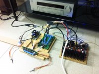
I had it running in mono-configuration a couple of weeks ago and I finally assembled the second channel yesterday (I got the kit from Siva). The amps have a DC-current of 3.5-5 mV (left channel) and 4-7 mV (right channel) - my multimeter isn't so good so the result did some "changing" while measuring. After half an hour of "slightly louder than normal" playing the LM3886 measures at 39°C and I have around 45°C in the area of the zener-diodes (is this normal?).
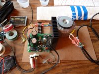
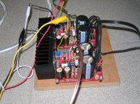
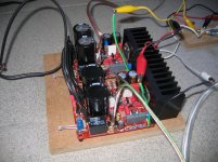
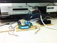
I still have to improve the wiring but I was eager to test the amp with the volume control and input switcher. There is nearly no hum (if muted all there is is silence ! ). I got some hum when I completely disconnected the input wires but as I said this issue will be addressed the next few days with the wiring (I guess this is the main problem). I attached some pictures of the amp running.
To say something about the sound: My Needle RS show bass and punch they never showed with my old Sony Receiver (you might see it in the pictures). I'm very pleased with the performance of the amp. As it is the first amp I assembled on my own, I think I'll have a good glass of wine after lunch .
Many thanks to Siva for the support and all of the people who invested so much time in this amp and posting their ideas/questions/answers in this forum.
Best regards
Sven
(As you see I decided to post it here ).I had it running in mono-configuration a couple of weeks ago and I finally assembled the second channel yesterday (I got the kit from Siva). The amps have a DC-current of 3.5-5 mV (left channel) and 4-7 mV (right channel) - my multimeter isn't so good so the result did some "changing" while measuring. After half an hour of "slightly louder than normal"
playing the LM3886 measures at 39°C and I have around 45°C in the area of the zener-diodes (is this normal?).I still have to improve the wiring but I was eager to test the amp with the volume control and input switcher. There is nearly no hum (if muted all there is is silence ! ). I got some hum when I completely disconnected the input wires but as I said this issue will be addressed the next few days with the wiring (I guess this is the main problem). I attached some pictures of the amp running.
To say something about the sound: My Needle RS show bass and punch they never showed with my old Sony Receiver (you might see it in the pictures). I'm very pleased with the performance of the amp. As it is the first amp I assembled on my own, I think I'll have a good glass of wine after lunch
.Many thanks to Siva for the support and all of the people who invested so much time in this amp and posting their ideas/questions/answers in this forum.
Best regards
Sven
Attachments
Thanks a lot . But I enjoy listening at the moment and have some parallel projects running. So, I'm happy that it works. If I come to think about "pimping" the My_RefC I think there are so much ideas here in this forum that I'll have enough to read and to try out.
But first I want to enjoy the amp as it is and probably give it a nice enclosure.
Best regards
Sven
. But I enjoy listening at the moment and have some parallel projects running. So, I'm happy that it works. If I come to think about "pimping" the My_RefC I think there are so much ideas here in this forum that I'll have enough to read and to try out.But first I want to enjoy the amp as it is and probably give it a nice enclosure.
Best regards
Sven
Let me suggest the Mundorf power caps and siva's LFO1 as items to consider if and when you want to bump it up a bit.
Goood job Sven! Hey, dont let that big film cap get in the way of best sound. Either remove or use something better.
Two spot-on suggestions.
I know you're enjoying your brand new My_Ref and with Siva's premium BOM you're starting from a very good point...
... but one thing, IMHO, you should consider to do before casing it.
Replace R13 with a Mundorf Zn 1.2uF 250V, you won't regret.
Or at least search on eBay a much chepear NOS Vishay MKC1862 1.5uF 63V, not as detailed and transparent as the Zn but delicious.

- Status
- This old topic is closed. If you want to reopen this topic, contact a moderator using the "Report Post" button.
- Home
- Amplifiers
- Chip Amps
- MyRefC build guide