My previous power amp is 12x and it allowed me to listen with vol at 12 o'clock, with very nice sensitivity of the vol. In comparison, 31 times of the MyRefC is quite a lot more for me on 96dB speakers... All the resistors seem to be in the right places. I guess I won't be messing with anything, but the sensitivity is less than ideal for my application. I'll give it a propoer listen tomorrow. ")
'There won't be any room for stand offs, unless they are <0.95mm high.
I envisage a double layer of thick insulating tape to keep the soldered pins from touching the aluminium chassis floor. But, will the lid fit without buckling or crushing?'
Andrew, have you got space to mount the smoothing caps off board, lying down...
Or use a hole saw to put holes in the top of the case with the tops of the smoothing caps poking out?
Too messy for you perhaps?
Bill
More cap questions:
I am still soldering away and making good progress. This is really fun. I think this one is obvious but, to verify, is C1 the unlabeled 220uf cap on the lower left hand corner of the board?
C4 and C5 came supplied with 10 mm lead spacing and the circuit board has 7.5 mm spacing. How are you dealing with that?
TIA,
rick
C9, C14, C1 & C2 are our 220uF. The unlabeled 220uF is right next to C2.is C1 the unlabeled 220uf cap on the lower left hand corner of the board?
Still head down and soldering stuff on board number one of my 6 channel project - my plan being to fit the whole thing into one custom case and use 3 of these trafos - when I suddenly thought that it might not be such a good idea to have all that stuff using just one 13A IEC?
Could someone advise me about this or maybe suggest any other reasons why this is not such a good idea. I haven't ordered the trafos yet and haven't even started the case, so it's not too late to alter my plan.
Thanks
Gary
Could someone advise me about this or maybe suggest any other reasons why this is not such a good idea. I haven't ordered the trafos yet and haven't even started the case, so it's not too late to alter my plan.
Thanks
Gary
Gary
I like the idea of all in one case because you will do less metal work and it will cost less overall.
I otherwise would prefer multiple cases. Grounding will be easier if you have a problem. Can you imagine tracing down anything in there if you have an issue on one or more channels? I mean, maybe if it was 30" wide and a foot or more deep it might be easy to work around in but otherwise, with channels stacked on top of each other or real close together it is going to be a pain later.
Uriah
Those transformers are great. You might consider a few more VA but they will do the trick and the Europeans seem to be happy with that brand. Us Americans are jealous because we wish we had nice encapulated trafos like that.
By the way, Antek now sells enclosures for trafos but you have to pot it yourself.
Uriah
By the way, Antek now sells enclosures for trafos but you have to pot it yourself.
Uriah
where are your speakers?
Why do you need all the amps in the same chassis?
I plan on replacing my 5 channel amp that I use for surround sound with something more capable with music. The reason for the extra channel is the possibility of bi-amping the front 3 speakers in the future and then adding another 2 channels for the rears.
They haven't got to be in the same chassis, I just liked the idea of it and it seems more aesthetically pleasing. Also, Uriah's point about the work and cost is relevant as I'm trying to fund this project with the sale of my current amp.
..I otherwise would prefer multiple cases. Grounding will be easier if you have a problem.
Hmm.. I hadn't thought too much about grounding yet, I was going to read up about it when I came to connect it all together, maybe I'll go and do some reading now and save a possible headache later. Thanks.
I know it will all be a tight fit, but my plan is to mount the boards vertically on their shortest edge with the LM3886 at the top and put them into the case like a row of dominoes along the back, with the trafos in a row along the front. Even with 10mm pcb mounts - to allow c21 to be fitted underneath - it will all fit into a case 430mm wide and only just higher than the length of the boards whilst still getting good access to everything. Also, I can then use a single heatsink for all 6 channels that will form part of the lid. It will be a bit hefty though.
My previous power amp is 12x and it allowed me to listen with vol at 12 o'clock, with very nice sensitivity of the vol. In comparison, 31 times of the MyRefC is quite a lot more for me on 96dB speakers... All the resistors seem to be in the right places. I guess I won't be messing with anything, but the sensitivity is less than ideal for my application. I'll give it a propoer listen tomorrow.
Assuming your pot is being used simply as a potential divider of the signal (the 'standard' way) then placing a resistor in series with the pot should have the effect you are seeking. A value of about 1.5 times the value of the pot should reduce the effective gain from 30 to 12. For example, if you have a 20K pot then put a 33K in series.
signal -> 33K -> 20K pot -> ground; signal take off from the wiper.
Cheers
Geoff
....when I suddenly thought that it might not be such a good idea to have all that stuff using just one 13A IEC?.....I would be concerned if you draw a continuous 13A @ 240VAC...
As for all in one case, if you take your time and carefully layout the parts you can do it.
Those transformers are great. You might consider a few more VA but they will do the trick and the Europeans seem to be happy with that brand. Us Americans are jealous because we wish we had nice encapulated trafos like that.
By the way, Antek now sells enclosures for trafos but you have to pot it yourself.
Uriah
I'm using one 225VA Nuvotem per channel. Should do the trick!!
These are really nice quality and recommended!I'm using one 225VA Nuvotem per channel. Should do the trick!!
One of those on its own would be good to power both channels
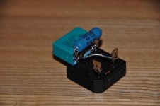
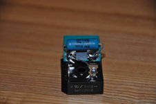
Questions about ground breaker
I have built a ground (loop) breaker Like the one Regi suggested from the ISP site Earthing (Grounding) Your Hi-Fi - Tricks and Techniques .
1) I don't understand how this device works or how I can test that it is working correctly?
2) I read that I should have used crimped connectors rather than solder, I understand the thinking here, but is it really necessary?
3) I should use one for each channel?
Can someone kindly point me towards a method to test this device and perhaps a little reading which might help me understand the principle of how this works? I have two decent DMM's, a dc bench supply to 32 volts, a variac, (and isolation transformer), and a bulb tester.
I don't understand how the amp works either but I can test that with my ears...this is a safety issue! I want to be sure my grounding is secure.
Thanks
Bill
Attachments
One of those on its own would be good to power both channels
Now that would be handy.... nah, dual mono all the way!
I thought you needed 160VA per channel?
Except, I ordered chassis the day before the kit arrived. The smoothing caps + PCB thickness is only 1mm less than chassis height. Oops.
Sounds like that chassis is too tight. The Panasonic 10,000uF capacitors have a vent on top. An application note published by Panasonic specifies a minimum of 3mm space above the capacitor to avoid blocking the vent. Here is a quote from the application note: "If the space is smaller than the requirements, then the pressure valve may not operate
properly, leading to an explosion." That would make it a safety issue so I wanted to alert you (and others) not to block the vent. Here is another issue to consider: "Exterior sleeves or lamination covering capacitors are for indication purposes only and do not guarantee electrical
insulation."
- Status
- This old topic is closed. If you want to reopen this topic, contact a moderator using the "Report Post" button.
- Home
- Amplifiers
- Chip Amps
- MyRefC build guide