It's easy enough to shape the legs so that the resistors sit horizontally, albeit just off the board.
Something like this:
Attachments
I started yesterday putting together one of the boards. I have had no problems with most of the common issues:
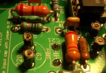
-I took a different approach for the resistors. I preferred to place the vertical rather than horizontal with the legs bent, so there is almost no risk of touching and adjacent component. I can see two resistor's legs too close from each other in this last Dario picture.
-I have drilled a new hole for R3 heatsink and now it doesn't touch any component. No need to trim or bend any fin. I am soldering the opamp directly to the board, so there are still around 3-4mm of clearance on top of it.
-I have soldered C21 under the board, and it left enough free space for C9 (Blackgate) to fit well. It will sit on the board and on C21 solder pads, so it doesn't vibrate of hangs on its legs. It is firmly seated.
-I placed C4 using C17 and C18 pads (not actually used), so it fits better AND doesn't touch R3 heatsink. This last one is the most relevant point, be careful with the heatsink.
-As an advice, remember to solder component's legs on both side of the board. It will provide a bigger contact surface for better electrical performance and a higher reliable mechanical performance.
-I first installed resistors, capacitors, relay and spades (all components not ESD susceptible, most of them). I will clean it thoroughly with isopropilic alcohol and a toothbrush. This will save me any troubles of frying a semiconductor because of brushing it with a plastic brush. I will solder then the LM318, LM3886, the transistors and the diodes, and leave the board with that little bit of flux. It is the best balance between having a clean board and having no risk.
So far, all audiophile components bringing any drawback have been succesfully solved.
Regards,
Regi
I took a different approach for the resistors. I preferred to place the vertical rather than horizontal with the legs bent, so there is almost no risk of touching and adjacent component. I can see two resistor's legs too close from each other in this last Dario picture.
Regi, if your approach makes you feel safer, good, but my MyRef is working since the last Group Buy... no problems at all.
Obviously with the 'orizontal bent' approach some care is needed.
")
As soon as I get homecould you post a pic of the heatsink installation?
Of course, your choice is good and will work alright. Just a matter of personal choiceRegi, if your approach makes you feel safer, good, but my MyRef is working since the last Group Buy... no problems at all.
Obviously with the 'orizontal bent' approach some care is needed.
Regi and other builders,
Be careful with Blackgate C9 if C21 is under the board. I found this arrangement fits the best, but be certain that the C9 leads are not touching C21 pads. I put a thin piece of foam under the Blackgate, which insulates it from C21 pads and any other accidental contact, and provides some reduction of vibration as well.
Perform a thorough visual inspection of all leads, especially those bent resistors, before applying power.
Peace,
Tom E

Thank you for the advice. I can clearly see that both pads stay away near 10mm away from each other, so I am safeRegi and other builders,
Be careful with Blackgate C9 if C21 is under the board. I found this arrangement fits the best, but be certain that the C9 leads are not touching C21 pads. I put a thin piece of foam under the Blackgate, which insulates it from C21 pads and any other accidental contact, and provides some reduction of vibration as well.
Perform a thorough visual inspection of all leads, especially those bent resistors, before applying power.
Peace,
Tom E
I was worried about it staying hanging, but when I bended the legs and soldered it to the board, it was kept quite firm, you can't move it. But it is easier and more practical to use somethink like your pads.
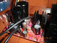
Well, I have one channel sounding. I don't like to judge equipment by listening only to one speaker and from a not already burned in amp, but at first sound is noticeble improved from my previous gainclone. More pleasant to the ear.
I will take better pictures, but finally the heatsink fits really well. And at standard volumes, both heatsinks stay a bit warm above ambient temp.
Regards,
Regi
I will take better pictures, but finally the heatsink fits really well. And at standard volumes, both heatsinks stay a bit warm above ambient temp.
Regards,
Regi
Attachments
Ok, I ordered 2 new lm318 from digikey ( damn that was quick) and low and behold I'm all powered up. So the only conclusion that I get from this is that the silk screened one that came with the kit in my picture the one on the right and the 5 that I bought are all bad.............weird, so at least now I can move on in this build. BTW should C9 leads be as short as possible?
Paul
Paul
The length of C9 leads doesn't matter so much as the stability of C9 and the safety of the leads (isolation from touching anything else). Keeping leads short is always wise, but don't worry about an extra quarter of an inch or so. If they're much longer than the diameter of the cap itself, that might be too long. Just make sure that the cap can't vibrate or rock around and stress the leads, as they may break. It would be far better to have them slightly stressed and unable to move than to have them relaxed and that big cap flopping around.
Peace,
Tom E
Peace,
Tom E
The length of C9 leads doesn't matter so much as the stability of C9 and the safety of the leads (isolation from touching anything else). Keeping leads short is always wise, but don't worry about an extra quarter of an inch or so. If they're much longer than the diameter of the cap itself, that might be too long. Just make sure that the cap can't vibrate or rock around and stress the leads, as they may break. It would be far better to have them slightly stressed and unable to move than to have them relaxed and that big cap flopping around.
Peace,
Tom E
Thank You
Paul
Proper solder joint
I am soldering up the resistors on my boards and all is going well. I am curious if solder is supposed to flow through the hole and and build up on the labeled side of the board. All of my joints look good from the back side but some have flowed through the hole and look nice on the front side of the board too. Others don't quite flow that far but still look like good joints from the back side. Is it important to have solder flow through the hole and build up on the front side? How does one control whether or not that happens every time?
TIA,
rick
to get the reverse side of a through hole plated PCB to solder the reverse side and the leg of the component must be up to soldering temperature.I am soldering up the resistors on my boards and all is going well. I am curious if solder is supposed to flow through the hole and and build up on the labeled side of the board.
This will require more time in heating the joint and/or a higher soldering bit temperature.
If the component cannot come to any harm from a more extended soldering time then try holding for longer, sometimes you see the top meniscus dissappear as the bottom side fills out. A touch more solder and you've done both sides.
For transistors and other semiconductors, I go back and retouch the reverse side after all the joints have cooled down.
If you clip a heatsink around the component leg, you can more safely apply heat for longer. But this clipping operation seriously slows down production.
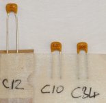
Yes, labeled correctly.... can someone confirm I have these caps ID'd correctly.
Hopefully this might help others too.....
See attached picture.
I replaced the 220pF (C12) ceramic 2.5mm pin pitch with a Wima MKP 220pF box case with 5mm pin pitch.
I replaced the 22nF with a Vishay 1837 22nF box type (both 5mm pin pitch). Quite a bit narrower and allows both C9 and C21 to be fitted to top side.
Last edited:
Is not REALLY critical to have solder flowing to the other side, but will give you better contact and better mechanical resistance characteristics.I am soldering up the resistors on my boards and all is going well. I am curious if solder is supposed to flow through the hole and and build up on the labeled side of the board. All of my joints look good from the back side but some have flowed through the hole and look nice on the front side of the board too. Others don't quite flow that far but still look like good joints from the back side. Is it important to have solder flow through the hole and build up on the front side? How does one control whether or not that happens every time?
TIA,
rick
What I do is to solder as normal, then flip the board, and solder the component on the other side's pad. This process will place solder on both sides and through the hole.
Regards,
Regi
I replaced the 220pF (C12) ceramic 2.5mm pin pitch with a Wima MKP 220pF box case with 5mm pin pitch.
I replaced the 22nF with a Vishay 1837 22nF box type (both 5mm pin pitch).
Hi Andrew,
for C12, I've had a report on a good improvement using a FKP2, probably MKP2 is (quite) good too but the 1837 in C21 is, IMHO, a bad choice...
I've already tried it last year and FKP2 is FAR better and balanced...
Have you noted differences soundwise?
- Status
- This old topic is closed. If you want to reopen this topic, contact a moderator using the "Report Post" button.
- Home
- Amplifiers
- Chip Amps
- MyRefC build guide