Hi guys,
I
- I recieved 4 tiny little ceramic caps with my kits and I'm having trouble figuring out where two of them go. One came attached to a peice of cardboard and is labeled uc221, the other is loose with shorter legs and is labeled 100 on one side and K2J on the other.
- As added info could anyone tell me where the other two go, I installed them in C12 and C21, but would like to make sure before I'm done and fire them up.
PJN
I was in the same quandary and asked here. If I have it right, the first two numbers on the capacitor are its value and the 3rd number represents the number of zeros you'd add after the value. So, the 22 1 capacitor is 220 pico farads and belongs in the C12 position. the 10 0 labeled cap is 10 pico farads and belongs in C34. The one labeled 22 0 is a 22 pico farad cap and belongs in C10.
I am not sure, but I think I received only 3 of those tiny caps so you might have gotten an extra which is completely understandable when packaging up so many kits.
hth,
rick
...you might have gotten an extra which is completely understandable when packaging up so many kits.
hth,
rick
LOL
I got an extra 'dime' (10 cent american coin) in my shipment...
it's easy to bridge connect the 4 resistors (2off 22k and 2off 47k) onto a plugboard.
apply 10 or even 60Vdc from top to bottom, i.e. to the junction of the two 22k and the junction of the two 47k.
Now measure the mVdc difference across the bridge, i.e. black probe to one 22k+47k junction and red probe to the other 22k+47k junction.
Now swap out one 22k for the spare 22k. is the mVdc difference bigger or smaller. Keep the swapped resistor in place and now put back the original 22k to replace the one 22k that was not originally swapped.
Is this the lowest or highest mVdc difference.
Now put in the two 22k that gave the lowest difference.
check the mVdc again.
Now swap the two 47k across with each other. Is the mVdc difference bigger? If yes return the 47k to where they were.
You now have the 22k:47k ratios at their closest match.
The pair of 22k&47k on one side of the bridge stay together.
The other pair of 22k&47k also stay together.
You can see how these pairs fit into the MyRef schematic. Both 22k & 47k have a common junction. It's those common junctions that must be maintained in the Howland current pump. Doing that gives the highest impedance available from that set of 5 resistors.
Thanks AndrewT for the wheatstone bridge tutorial. I, boneheadedly, mixed my resistors together not realizing the matched pair were separate. I used my super cheapo multimeter to measure and was able to ID the matched pairs in 2 of my 4 kits. The other 2 kits weren't so clear with my meter. I used the bridge to check out and optimize the unknown kits and then went back to the 2 kits I was confident in and checked them. Although I am sure they were well within tolerance, I was able to further optimize R5/R6 and R8/9 with the bridge. I simply taped the resistors to the benchtop and using alligator leads and a 12vdc supply (everyone has one of those in their garage, right?) to mix and match until I had the best combos. It took very little time and should maximize performance. Highly recommended.
thanks,
rick
Every LM318 I ordered was a Nat Semi. I had to order from no less than 4 different sources to get them all for some reason. Anyway, all Nat Semi. My LM318 look like your LEFT IC with only an etching in the surface and no silkscreen on the top like your RIGHT IC.
So from what you have said we can probably rule out a dead LM318 but we can rule IN that the proper LM318 will do the trick. I honestly wonder if the silkscreened one is a real Nat Semi chip. I know I sent it to you but obviously I am not in the fake IC business and obviously you have two supposedly Nat Semi ICs of which only one works.
Your other 5 that DONT work: Where did you get them from and do they look like the silkscreened one?
From what I remember from the previous buy and from earlier posts in the original thread a lot of people have had clicking trouble. I wonder if your home voltage is lower than normal and if for some reason its fine for the one IC and right there on the line of fine/not fine for the other ICs.
Troy I think you have helped a few people with this. Wasnt there a resistor that folks lowered the value of when they had the clicking trouble?
The sink is just way to small and the sinks on your Caddocks are going to let your Caddocks fry. This is basically a non starter. If you leave in those heatsinks they will fry if they have not already. Both the LM3886 and the Caddock but the Caddock first.
I also wonder where is the 470k resistor near the opamp on the left side. Maybe you mounted it below.
All 5 lm318 look like the silk screened one. I'll get different sinks on to those caddocks right away, and I'm building a heat spreader as we speak for the 3886's.
Thanks
I checked all my inventory.
Uriah, not a single error. Brilliant!!
I pulled out the 3off 47k and the 3off 22k
The 2000 count DMM set to 200.0k could not tell the odd one apart. the LSB was flickering and could not reliably resolve which was different
Series coupled the three 47k and applied 590mV across the string.
Measured the voltage drop across each 47k, 196.2, 196.2, 197.0
Pretty obvious which is the unmatched of the three. and also why the 2000count DMM could not tell them apart. Only 0.4% spread between all three.
set the 197 apart to become R20.
strung the three 22k together and measured the voltage drop across each.
188.0, 187.7, 187.6. Again the 188 was set apart to become R43.
Now set up the 4 resistors in bridge formation.
Applied 12V across top to bottom. VdiffA across the middles ~1.0mV.
Increased the supply voltage to 63V and VdiffB=8.5mV
Swapped the two 47k. Vdiff=1.0 and slowly stabilised to VdiffC=1.6mV The heating effect of 115mW dissipated between all 4 resistors was having an effect.
Now added a 1r0 between the two top resistors.
Clipped +63 to one side of 1r0, short wait till stabilised VdiffD= -2.3mV.
Shorted out the 1r0 and VdiffE=-1.6mV
Moved the +63 to to the other side of 1r0. VdiffF =-0.9mV.
Shorted out 1r0, VdiffG=-1.6mV
The shorted 1r0 in the last two arrangements (VdiffC=VdiffE=VdiffG) confirms that the VdiffC=1.6mV
VdiffF=-0.9mV is the minimum Vdiff. This is the best ratio match for the 22k&44k for the bridge.
Now as a final check I add a second 1r0 parallel to the first to insert the 0r5 that our modified Howland CCS uses. With 0r5 shorted out Vdiff~-0.6mV and with 0r5 in circuit, Vdiff=-0.9mV Notice I am starting to get some variation in results as we close in on precise Wheatsone Bridge balance.
I can see from these last two results that adding 0r5 changes Vdiff by 0.3mV whereas changing by 1r0 made a Vdiff change of 0.7mV This confirms our readings are about right.
If I wanted Vdiff=0.0mV with 0r5 in circuit, I would need to add ~1r5 to the other side of the bridge in series with the other 22k.
Well, let's test it.
I now have a bridge with one side consisting of 0r5 + 22k + 47k.
The other side consists of 1r5 + 22k + 47k.
Vdiff=+0.1mV. The correction resistor of 1r5 changed the Vdiff from -0.6mV to +0.1mVI short out 1r5 and the Vdiff returns to -0.6mV
I have added a slightly too large correcting resistor.
No worries. Here's why.
As supplied by Uriah, his matched resistors gave a worst case Vdiff=8.5mV and a best case Vdiff=1.6mV simply by swapping around the components as supplied.
Then when 0r5 is added (to mimic the effect of the Caddock 0r5 in MyRefC) we find the better side to add it to. We reduce the Vdiff to ~1mV.
We find a correcting resistor of 1r5 to be too big.
That 1r5 is only 0.007% of the 22k. I will leave Uriah's supplied resistors as he sent them.
Trying for better than 0.007% is a waste of my time and yours, particularly since no one came back to answer my two questions.
But one final comment. Vdiff best = 0.6mV and Vdiff worst 8.5mV. That is worth the few minutes it will take to find the right way to combine them.
Where do we fit them?
Take the side of the bridge with 0r5+22k+47k
These resistors become R3, R8, R9
The other side of the bridge uses up the two remaining positions of R5 & R6.
Last edited:
follow on from post 149
Hi,
I set up the second channel bridge last night. Went through exactly the same procedure as post149 and determined a worst case Vdiff=15.3mV and a best case Vdiff=3.2mV
Not quite as good.
BUT!
there is a big difference between the two.
This time the correction resistor needed to bring Vdiff=0.0mV is on the same side of the bridge as the 0r5. i.e. the 22k on this side leg is too small.
I could leave it like that because the correction resistor of 6r8 is still 0.03% of the 22k.
But because the 22k is too small the output impedance of the Howland would be -ve. The other channel is +ve output impedance.
I don't know what effect this might have on sound, so I am going to make both Howlands have a +ve output impedance.
As I said the correction resistor has a value of 6r8.
The other channel has a missing 1r5 (I did not fit it). If I change the 6r8 to 8r3 then this corrected side will have R8 bigger than the other side. Now both channels are expected to have a Vdiff=~-0.4mV
This can be checked on the circuit board after you have started soldering.
Place all the resistors. Leave out C10, Leave out C30, Leave out IC1, Leave out IC2.
Place a temporary link from the open end of R9 to the empty pin6 of IC1.
Apply the zero volt connection of your test DC PSU to this link.
Apply the +40Vdc to the empty Pin3 of IC2.
Now clip DMM red probe to IC2 Pin 10 and black probe to IC2 Pin9.
Read the Vdiff of the bridge.
Yes, the Howland and the improved Howland actually have a Wheatstone Bridge in the circuit and IC2 reads Vdiff to work out what current to send to the speaker.
I would suggest that both PCB assemblies read the same polarity PIN 9 to 10 and that Vdiff<5mV. The lower the better, to a point.
BUT!
do not go too close to +-0.1mV. In this region tiny differences in temperature on any of the 22k/47k bridge resistors will change the bridge ratio. The Howland could swap between +ve output impedance and -ve output impedance. I don't know if this would be audible or measurable, but I am playing safe and aiming for -0.3mV to ensure that both channels have a similar high output impedance and that both channels stay +ve output impedance over a range of different temperatures on the well spaced 4 bridge resistors.
I am going to go and check that these instructions actually work later today.
Await confirmation after my swim.
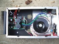
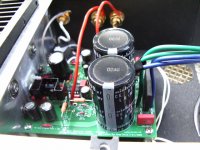
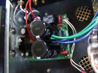
To serve as inspiration for those of you building amps, here are a few poor photos of my "ultimate BOM" amps. These are not quite identical to the kits recently offered, but they share many of the same parts, and certainly the same basic circuit.
Some elaboration on the pics: as you can see, the trannies are only an inch or two from the power supply side of the boards. I didn't twist any leads, didn't use any shielding on input or output wires, and my amps are completely silent. I mean deep, black silence. No extraordinary measures are needed to achieve these results, other than keeping leads short and not crossing signal wires with power leads.
The enclosures are the cheapest available thin aluminum. The heatsink is nearly as big as one entire wall of the enclosure, mounted on one short wall, coupled through the enclosure wall to the chip with a nylon screw and insulating pad and lots of thermal grease, spread in a skin-thin layer.
The top of the enclosure is the wooden top cut out of an old Yamaha receiver with a very large metal grille for ventilation. Nothing inside these amps ever gets more than warm.
The black material is Sound Coat from Parts Connexion. It also covers about two-thirds of each long wall. It applies directly to the aluminum and damps it very effectively. The transformer is mounted on a Spectra Dynamics Deflex Toroid Support, also from PC.
The Fostex film & foil input cap is just visible, close by the side of the board, wrapped in neoprene foam and attached to the enclosure with a cable tie. The leads can be seen easily because they're wrapped in white teflon plumber's tape.
I used EAR small isolation feet, also from PC, under the enclosure. Despite its thin wall construction, the enclosure and all components seem effectively isolated from internal and external vibration.
The input jack and binding posts are Vampire copper base (not brass) with gold plating. The hook-up wire is OCC solid copper. All connections are soldered directly to the board.
The LED is mounted on the front of the enclosure, connected by the two white wires crossing under the power leads. All four walls of the enclosure contain some element: one long wall has input and output connections, very near that part of the board; the other long wall has only the LED; one short wall has the heatsink; the opposite short wall has fuse, IEC, and power switch, a heavy-duty toggle that "snaps" real nicely when switched.
You can choose to make your enclosures more attractive, but the most complicated arrangement will probably not function any more effectively than this simple, inexpensive one.
I have noticed these amps are very responsive to better power cords. I built my own, and they sound much better than any "standard" molded cord supplied with other equipment.
Good luck with your builds!
Peace,
Tom E
Attachments
Last edited:
I can hardly understand what Andrew is doing or why, much less attempt to do it. I purchased matched pairs of PRP resistors from Parts Connexion (I think it cost $5 extra per value). Uriah's are probably just as well matched, perhaps even better. I checked them on my own crudely constructed Wheatstone Bridge and found them to match very closely.
I am interested to learn if Andrew's procedure yields better sonics. I don't believe the amp could function any more efficiently, as the chips in mine are barely warm to the touch (certainly also a function of heatsink efficiency) after cranking into B&W 802's all day, as they're doing right now. They sure sound sweet.
Guys, just build 'em already and quit overthinking everything. Mauro knew what he was doing, and these better parts make them sound even better!
Peace,
Tom E
The enclosure is made by BUD, available from most electronics suppliers, model no. AC-408. It's cheap and crude. There is a cover available separately, but I chose to use something I salvaged from a junked receiver. Looking at these crappy boxes, you would never suspect that they contain amplifiers that are nearly the best you have ever heard.
The blue cap on the terminals of the toggle switch was installed to address to tendency of this amp to pass motor-start spikes on the mains. It is not very effective, and I still can hear pops when a large motor, such as my furnace fan, turns on. Now, during summer, no noise at all.
The amp itself is completely silent during turn on and off. That's what the relay is for, and it works very well.
Peace,
Tom E
1/2 watt PRP resistors?
Maybe someone else has asked this question; if so, please forgive me.
Five of my resistors are two wide for the holes in the board. One is the big 1 watt and the other 4 are the 1/2 watt PRP resistors. Is there a trick to putting them in without them looking dorky?
Maybe someone else has asked this question; if so, please forgive me.
Five of my resistors are two wide for the holes in the board. One is the big 1 watt and the other 4 are the 1/2 watt PRP resistors. Is there a trick to putting them in without them looking dorky?
- Status
- This old topic is closed. If you want to reopen this topic, contact a moderator using the "Report Post" button.
- Home
- Amplifiers
- Chip Amps
- MyRefC build guide