buy 63/37 solder in two sizes. The eutectic gives better and easier results.If i am using a 60/40 solder with flux core, is additional flux overkill?
Great Bill, you have done a great work. I will read them when I have time, and include them in the Documentation. But at a first glance, they look like an intensive analysis. I had lots of questions about the DC protection system that were not solved, now its the time ")
Andrew, revise your previous post quote about the relevant information posts. For any reason, they are posted in a wrong way, not showing right the links.
Andrew, revise your previous post quote about the relevant information posts. For any reason, they are posted in a wrong way, not showing right the links.
Thanks to all! Once I realized the 3rd digit on the capacitor is the multiplier, then all capacitors fell into place. Other newbies take note.
2 of the 4 kits I received had 5% tolerance on C30 rather than 2.5% per the spec of latest BOM (Thanks Bill_P). Should I worry about that or happily move on.
TIA,
rick
2 of the 4 kits I received had 5% tolerance on C30 rather than 2.5% per the spec of latest BOM (Thanks Bill_P). Should I worry about that or happily move on.
TIA,
rick
Because Andrew has asked me to, I will re-post Uriah's post of most useful resource links. I cannot quote it because the forum will not parse the URL links and it will show like the previous Andrew's post.
So, my next post IS NOT MINE. It is Uriah's Thank's to him, one more time.
So, my next post IS NOT MINE. It is Uriah's
Thank's to him, one more time.Here are some questions and answers I put together before I decided whether to run the group buy or not. A huge amount of information.
http://www.diyaudio.com/forums/chip-amps/54571-my-audiophile-lm3886-approach.html
Original introduction and subsequent design thread.
Can I ask the orginal designer some questions? No. He is a good guy but he no longer participates on this forum.
http://www.diyaudio.com/forums/chip-amps/54571-my-audiophile-lm3886-approach-299.html#post1666211
Thats for gerbers, boms, etc.
http://www.diyaudio.com/forums/chip-amps/54571-my-audiophile-lm3886-approach-303.html#post1681700
Single sided for etching.
The Dim-bulb Radio Tester
Lets just say that when firing it up for the first time, if you dont use this or a Variac, then dont blame anyone else if something goes 'poof.'
http://www.diyaudio.com/forums/chip-amps/54571-my-audiophile-lm3886-approach-305.html#post1685919
24V secondaries are best but 22V would be fine..
http://www.diyaudio.com/forums/chip-amps/54571-my-audiophile-lm3886-approach-308.html#post1690023
A discussion about grounding as it can be a bit confusing with this amp.
http://www.diyaudio.com/forums/chip-amps/115698-understanding-star-grounding.html
Grounding - Read this please
http://www.diyaudio.com/forums/chip-amps/54571-my-audiophile-lm3886-approach-309.html#post1696302
What pot to use?
http://www.diyaudio.com/forums/chip-amps/54571-my-audiophile-lm3886-approach-312.html#post1994728
Many caps on the board are .22uf but spec'd for .1 in Mauro's schematic. Why the change?
http://www.diyaudio.com/forums/chip-amps/134726-new-my-ref-rev-c-thread-84.html#post1894099
Dont try to improve it with the normal "tweaks". This amp is tweaked already. Leave the opamp alone. Just stop. Resist.
http://www.diyaudio.com/forums/chip-amps/134726-new-my-ref-rev-c-thread-82.html#post1884786
Fuse and switch installed correctly.
http://www.diyaudio.com/forums/chip-amps/134726-new-my-ref-rev-c-thread-78.html#post1881513
what it looks like assembled.
http://www.diyaudio.com/forums/chip-amps/134726-new-my-ref-rev-c-thread-78.html#post1881527
Can I use different diodes instead of the recommended rectification?
http://www.diyaudio.com/forums/chip-amps/134726-new-my-ref-rev-c-thread-76.html#post1853965
Should I put fuses on the secondaries?
http://www.diyaudio.com/forums/chip-amps/134726-new-my-ref-rev-c-thread-74.html#post1829568
DC offset at output of amp. Whats okay? How do I measure it?
http://www.diyaudio.com/forums/chip-amps/134726-new-my-ref-rev-c-thread-73.html#post1828475
I want the technically perfect heatsink. If you just want a guess then us a 2.5"x2.5"2" cpu heatsink.
http://www.diyaudio.com/forums/chip-amps/134726-new-my-ref-rev-c-thread-72.html#post1828150
Is it worth the build?
http://www.diyaudio.com/forums/chip-amps/134726-new-my-ref-rev-c-thread-66.html#post1817872
I want to swap my own caps. How should I do that so I dont end up over soldering the board and lifting a trace?
http://www.diyaudio.com/forums/chip-amps/134726-new-my-ref-rev-c-thread-53.html#post1785029
I have noise after putting in large input caps or just some hiss anyway, here is one explanation.
http://www.diyaudio.com/forums/chip-amps/134726-new-my-ref-rev-c-thread-48.html#post1783502
Should I do MonoBlocks? Well, I dont know but there is a discussion here.
http://www.diyaudio.com/forums/chip-amps/134726-new-my-ref-rev-c-thread-45.html#post1775852
I like cap swapping. Anything else I might like ?
Picasa Web Albums - Peter - RevC Measurem...
Some REVC measurements from Peter
From Mauro's webpage:
Passing band (typical-3db): 2Hz-70Khz
* The maximum power (8ohm): 40Wrms
* The maximum power (4ohm): 56Wrms
* Damping factor (8ohm): >200
* Relationship S/N (600ohm): >96 dB not weighed
* Typical THD (20Hz-20Khz, 1-40W 8ohm <0,05%
http://www.diyaudio.com/forums/chip-amps/134726-new-my-ref-rev-c-thread-85.html#post1894413
Cap recommendations by Dario
I have a pic of the top of the board.. pdf below
Also an eagle schematic
Uriah
Well, here I come with the latest additions to the project Documentation:
Bill_P has provided us with some impressive measurements and writings. Of course they've been added to the compilation of the most relevant documents from this project. Thank's to him for this great effort and help.
-Added in the Bill_P folder a 20 pages paper extensive description about the behaviour of the DC protection system with simulation measurements.
-Added in the Bill_P folder some measurements he took from the 10 most relevant passive components of the circuit.
MyRef_C_Ultimate_Documentation_v1.5.rar
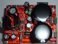
I have finished building the first board of a stereo pair and have some comments on how the build went.
In my amplifier box the back wall of the enclosure is the heatsink. The amplifier board mounts to the bottom plate and the LM3886 is fastened to the back wall (heatsink). For this to work the LM3886 must protrude past the edge of the PC board to keep the board from touching the heatsink before the LM3886 does. Unfortunately the board protrudes further than the back side of the LM3886 because the layout placed the LM3886 too far to the interior of the board. I had to straighten the leads of the LM3886 and reform them to make the chip protrude past the board edge. Depending on your heatsink configuration this may or may not be a problem but is something to keep in mind.
The heatsink for the Caddock resistor needed a fair amount of surgery. On the LM318 side two fins were removed and one fin on the LM3886 side. Wire cutter pliers are able to cut through the soft aluminum.
Capacitor C4 is supplied with 10mm lead spacing but the board layout is for 7.5mm. The location of C4 interferes with the Caddock heatsink so I formed the leads of C4 outward to span the holes for C17 and C18. Since C17 and C18 are not used, C4 was placed there to avoid the heatsink.
C5 is also a 10mm part with a 7.5mm board spacing. Forming the leads inward slightly allows it to fit in the board.
The Black Gate capacitor does not fit well in the board. The leads need to be formed inward and then it sits on R13 in an unstable position. I put two fiber washers under the Black Gate to raise it just above R13 and make the mount more solid.
R10 and R12 are supplied as 1/2W while the board takes the 1/4W size. Both resistors need the leads formed to fit.
In the relay circuit I used generic parts and avoided the cases where the supplied resistors are too large for the board layout. For the capacitors I used nonpolar Nichicon ES parts and put clamping diodes across them on the bottom of the board. I had 25V capacitors on hand but anything 10V or more is suitable. I had intended to modify the board to put in a 24V regulator for the relay but it didn't turn out to fit well with the board layout. To correct the low supply voltage problem in this circuit I changed R14 from 470 Ohms to 68 Ohms. That powers the relay with about 23 volts with a 22V transformer in the power supply. For a 25V transformer try 100 Ohms and for a 18V transformer, 10 Ohms. The diodes were changed from 1N4001 to UF4002 since the circuit needs more than a 50V diode rating.
C21 will not fit on the top side of the board so it was placed on the bottom. The leads were bent at a 90 degree angle and the cap placed on its side. The original holes for C21 were used to solder the part in.
Overall the build went fairly well. The worst of it was reforming the LM3886 leads. Using audiophile parts caused a few issues with the fit but nothing that wasn't easily handled.
Bill P,
Unless there is something about these boards or LM3886 chips that is different from those in the last group buy, I don't understand your comment about the difficulty of mounting the chip to the enclosure. I mounted mine directly to the enclosure wall with no problem. Why can't the board touch the enclosure wall? If anything, that might stabilize it and damp it. Rookies: if you're bending leads to get parts to fit, make certain that none of them will contact anything else or protrude over the edge of the board, or poof!
You seem very technically astute, and I don't understand a lot of what you have analyzed and posted, but I think it's great that you're looking at this circuit closely. One thing really bothers me: if so much is wrong with the protection circuit, how come so many amps work just fine? How would the "problems" that you see manifest themselves? Are the diodes meant to be marginal and fail in case of other instability? I'm not doubting your conclusions, but the evidence is pretty overwhelming to the contrary. I use a 22v xformer, and I've turned my amps on and off hundreds of times and the relay keeps clicking along just as it should.
There is definitely some cutting and fitting needed to get these fancy parts to fit. The board was not designed for some of these parts. I think that 7.5mm lead spacing was not a good design decision, but it's not a deal breaker. After a couple builds, I got pretty good at bending the 10mm leads just right! Yeah, the BG is huge compared to the space allowed for it. I pushed mine off to one side near where the input cap is supposed to go, with "L" shaped leads, supported by a small piece of foam. Rookies: that big BG cap should not be allowed to just dangle loosely. Put something under it. I didn't need to remove as much material from the heatsink I used for R3. I wonder what's different?
Let us know how it sounds!
Peace,
Tom E
Awesome. Thanks Andrew. I hope the guys find and use the new thread.
edit: hmm the first and last link offer no information on building though...
Uriah
Here was the best source for information on the Rev_C build.
Twisted_Pair did an outstanding job with the first offering.
RevC Amplifier - Twisted Pear Audio Support
Tom, you raised several issues and there is no short answer to any of it. I work for a major corporation designing electronic assemblies (not audio). A given design might be sold a a rate of 50000 a year and a field failure rate of 5% is more than enough to call a halt to production. So if 95% of the units work, I have failed and will be called before an executive review board to explain myself. Obviously this is highly unpleasant and it is far better to design and test thoroughly beforehand. Is it reasonable to apply these standards to the audio hobby? Maybe not, but for me it's ingrained I guess.
The relay circuit uses several components outside the manufacturer's specifications. Even so, given the use of quality components with built in design margins, some or most of the units may work. But it is poor practice and not acceptable in my world. Regarding the diodes, it is not a case of purposefully selecting a weak component. There are fuses and other circuit protectors for that. I have measured samples of 1N4001's on a curve tracer and the breakdown varies all over the map. Some manufacturers seem to label some lots 1N4001 when they actually measure as if they are rebranded 1N4004 types with a 400V breakdown. The economics of producing one part that can be branded with several part numbers may dictate that decision. Regardless, the user can't know how much above the rated voltage a given 1N4001 will tolerate.
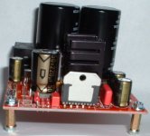
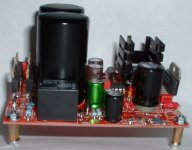
The LM3886 mounting issue is a question of mechanical force transmission once the screw is tightened to hold the chip against the heatsink. The screw wants to force the chip flat against the heatsink. The board sticks out further and hits the heatsink and tries to prevent the chip from flattening against the heatsink. These opposing forces put strain on the solder joints at the PC board and on the chip package. If the metal tab on the chip bends even microscopically, it can crack the chip die. Or the strain can cause the solder joints to fail over time. Or the chip may not achieve good contact with the heatsink since the lower part of the chip package will tend to pull away from the heatsink. In that case the thermal path from chip to heatsink will be poor and the die will run hot. In no instance is it an advantage to have the board touch the heatsink.
I removed more material from the Caddock heatsink on the LM318 side because I used an IC socket and do plan to try several different LM318's when the amp is up and running. Getting access to the socket to change op amps required a bit more space than if I had just soldered the LM318 to the board directly.
I will report my impressions about how it sounds but it's going to take a while to finish building it. Before it is installed in the system there are lots of bench tests I want to conduct. The amplifier circuit is really very complex with several nested feedback loops. No decent SPICE model exists for the LM3886 so the simulation part will have to be skipped. The wide range of values for R42 (see the PC board silk screen) is of some concern and I want to get a better understanding of how R42 affects the amplifier stability.
The relay circuit uses several components outside the manufacturer's specifications. Even so, given the use of quality components with built in design margins, some or most of the units may work. But it is poor practice and not acceptable in my world. Regarding the diodes, it is not a case of purposefully selecting a weak component. There are fuses and other circuit protectors for that. I have measured samples of 1N4001's on a curve tracer and the breakdown varies all over the map. Some manufacturers seem to label some lots 1N4001 when they actually measure as if they are rebranded 1N4004 types with a 400V breakdown. The economics of producing one part that can be branded with several part numbers may dictate that decision. Regardless, the user can't know how much above the rated voltage a given 1N4001 will tolerate.
The LM3886 mounting issue is a question of mechanical force transmission once the screw is tightened to hold the chip against the heatsink. The screw wants to force the chip flat against the heatsink. The board sticks out further and hits the heatsink and tries to prevent the chip from flattening against the heatsink. These opposing forces put strain on the solder joints at the PC board and on the chip package. If the metal tab on the chip bends even microscopically, it can crack the chip die. Or the strain can cause the solder joints to fail over time. Or the chip may not achieve good contact with the heatsink since the lower part of the chip package will tend to pull away from the heatsink. In that case the thermal path from chip to heatsink will be poor and the die will run hot. In no instance is it an advantage to have the board touch the heatsink.
I removed more material from the Caddock heatsink on the LM318 side because I used an IC socket and do plan to try several different LM318's when the amp is up and running. Getting access to the socket to change op amps required a bit more space than if I had just soldered the LM318 to the board directly.
I will report my impressions about how it sounds but it's going to take a while to finish building it. Before it is installed in the system there are lots of bench tests I want to conduct. The amplifier circuit is really very complex with several nested feedback loops. No decent SPICE model exists for the LM3886 so the simulation part will have to be skipped. The wide range of values for R42 (see the PC board silk screen) is of some concern and I want to get a better understanding of how R42 affects the amplifier stability.
Attachments
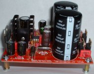
Thanks for the thorough explanation. Your professionalism is readily apparent, and all your comments make sense from that perspective. I'd like to see the quality of your solder joints! The completed amp certainly looks tidy on top.
In the future, please keep in mind that most of us, if not all, are rank amateurs, and we can hardly understand the workings of this thing, much less complicated circuit or component analysis. I look forward to your examination of the completed amp, but bring it down a notch, if you could, so we can all appreciate your hard work. I am eager to learn, but so far I'm just baffled by some of your contribution. It is pretty cool, though.
I'm sure your willingness to share your vast knowledge and insight will be an asset to the rest of the group. Me, I'm happy when sweet music and no magic smoke comes out!
Peace,
Tom E
it is down a different philosophy.One thing really bothers me: if so much is wrong with the protection circuit, how come so many amps work just fine?
I regularly run relays at 50% to 70% of rated voltage. But that needs the cap to give the relay a kick and ensure it pulls in hard and then relaxes,
That very well researched paper is based solely on the statement that the relay may have poorer conductance across the contacts if not run at rated voltage.
One has to decide whether to run the relay at rated voltage or at some reduced voltage.
I will be running it at reduced voltage. Possibly as low as 50% (12V) but I will also look at drop out time. It seems to me many of the RC timers are not well chosen.
I did appreciate all that time sequence research. It confirmed many ideas I have on the way timed relays operate, but I do it all (very slowly) by hand calculation.
Last edited:
it is down a different philosophy.
I regularly run relays at 50% to 70% of rated voltage. But that needs the cap to give the relay a kick and ensure it pulls in hard and then relaxes,
That very well researched paper is based solely on the statement that the relay may have poorer conductance across the contacts if not run at rated voltage.
One has to decide whether to run the relay at rated voltage or at some reduced voltage.
I will be running it at reduced voltage. Possibly as low as 50% (12V) but I will also look at drop out time. It seems to me many of the RC timers are not well chosen.
I did appreciate all that time sequence research. It confirmed many ideas I have on the way timed relays operate, but I do it all (very slowly) by hand calculation.
Just curious - why will you be running reduced relay coil voltage?
The timers are not precision circuits since they depend on transistor parameters like Vbe, Ib, and Hfe for thresholding. All the parameters change significantly with temperature and that affects timing too. The timer must not respond too quickly or it may cause relay drop-out when playing music at full power. What problems do you see with the time response of the circuit as originally designed?
running reduced voltage (long term) has the advantages of :
1.) drawing less current from the supply.
2.) relay running at lower temperature.
3.) relay drops out more quickly after loss of supply.
The 40ms delay before the relay loses it's supply is absurdly long.
<10ms would be much better to prevent bangs, cracks, pops and clicks getting to the speaker in event of mains failure.
The 220k and 100uF giving RC = 22seconds can be improved. It does not need to be that long under any circumstances.
Andrew,
Just a few comments and results of measurements here.
The relay tested with one amp DC through the contact measures 4.4 milliohms resistance (Kelvin 4 wire connection). Initially there was a transient change in the resistance when I lowered the coil voltage. After a minute or so it settled out and the resistance returned to its original value as measured at 24VDC across the coil. Letting the relay run for a half hour, the transient no longer occurred and the contact resistance did not change with coil voltage. 14.7 volts was needed to pick the relay and it dropped out at 4.1 volts. This is a sample of one at room temperature.
In my experience a pulse as short as 1 millisecond can be heard as a click through a speaker. The relay mechanical response time is specified as 5 milliseconds max so I doubt it will be possible to eliminate all speaker noise in the event of a transient.
Mains at 50 Hz will have a period of 20 milliseconds. If your objective is to drop the relay within 1/2 line cycle, that will be quite difficult and the circuit might misfire under small line disturbances that would otherwise not disrupt the amplifier.
The discussion about the microscopic detail of the relay and its driver is probably off topic for a general build thread and may not interest many members who bought the kit. If you have ideas for improving the protection circuit, I am interested in your ideas and will help with the investigation if I can. Maybe a new thread or direct PM would be a better venue for further discussion.
Bill,
-I didn't knew that, why C17, C18, C19 and C20 are not being used and supplied with the kit?
-Why are for the clamping diodes you placed under the board? What are they?
-I didn't knew about the problem of lack of supply for the relay. Is that a design issue from the beginning? Never heard of it...
-Neither knew that an 1N4001 is too low rated for this position.
Uriah, did you have the same problem as Bill when placing the LM3886 on the heatsink?
Andrew, is there any minimal disadvantage in running the relay at lower voltage than recommended?
I am waiting too for your thoughts of the RC timers, why they don't seem addecuate.
Bill,
-I didn't knew that, why C17, C18, C19 and C20 are not being used and supplied with the kit?
-Why are for the clamping diodes you placed under the board? What are they?
-I didn't knew about the problem of lack of supply for the relay. Is that a design issue from the beginning? Never heard of it...
-Neither knew that an 1N4001 is too low rated for this position.
Uriah, did you have the same problem as Bill when placing the LM3886 on the heatsink?
Andrew, is there any minimal disadvantage in running the relay at lower voltage than recommended?
I am waiting too for your thoughts of the RC timers, why they don't seem addecuate.
Some people think C17-C20 hurt performance rather than help. There have been discussions about this on the forum and maybe in the original group buy thread.
The clamping diodes are across the capacitors in the relay circuit. The explanation is in the PDF I posted.
The low supply voltage for the relay has evidently been part of the design from the beginning judging from the silk screen on the PC board showing component values.
The 1N4001 is rated too low and must have been a design oversight. Easy enough to change for those who are concerned about it.
My measurements indicate there may not be much disadvantage to undervolting the relay in the typical case. My own preference is to run near rated voltage and I have changed R14 to do that.
I agree with BillP.
The circuit as designed and in the PCB works.
The improvement offered by BillP is optional.
Whether one implements the improvement is down to whether or not one requires the speaker isolating relay to operate with a long term voltage of 100% of rated voltage or 62% of rated voltage.
The builder has to weigh up the pros and cons and decide.
AS IS, WILL WORK.
- Status
- This old topic is closed. If you want to reopen this topic, contact a moderator using the "Report Post" button.
- Home
- Amplifiers
- Chip Amps
- MyRefC build guide