I built me two LM1875 amps which have been going fine for a couple of weeks.
Today I built a third. Hooked him up to my junk-grade test speaker, switched on. Works, sounds fine, no problem.
So I hook him up to the woofer on a three-way speaker I made, with the other two amps on the other two speakers. Crossover is being provided by my PC. All three amps on the same PSU.
Sounds cool, everything's fine for an hour or so.
Suddenly -- the woofer jumps forwards and is straining to pop out the cabinet! That'll be DC on the woofer, no?
Naturally I switched off straight away. A visual check of the amp showed no signs of any shorted wires, no visible problem. The other two amps are fine.
What could cause this to occur? The only component difference in the latest amp is the electrolytics on the power pins. Could bad caps have murdered my amp like this?
I built me two LM1875 amps which have been going fine for a couple of weeks.
Today I built a third. Hooked him up to my junk-grade test speaker, switched on. Works, sounds fine, no problem.
So I hook him up to the woofer on a three-way speaker I made, with the other two amps on the other two speakers. Crossover is being provided by my PC. All three amps on the same PSU.
Sounds cool, everything's fine for an hour or so.
Suddenly -- the woofer jumps forwards and is straining to pop out the cabinet! That'll be DC on the woofer, no?
Naturally I switched off straight away. A visual check of the amp showed no signs of any shorted wires, no visible problem. The other two amps are fine.
What could cause this to occur? The only component difference in the latest amp is the electrolytics on the power pins. Could bad caps have murdered my amp like this?
My sincere condolence...
Can you provide a schematic of your amplifier?
1: Do you have an output zobel?
2: Do you use a output inductor/resistor in series?
Did you check the temperature from the chip time to time? And how hot was it?
Do you have a oscilloscope?
Big chance the cause of this sudden suicide is oscillation caused by the capacitive or inductive load from the cables in combination with the voice coil.
With kind regards,
Bas

My sincere condolence...
Thank you -snif!- it's a difficult time...

Can you provide a schematic of your amplifier?
Pretty much like the standard application in the datasheet.
2M2 across the input, 2u2 input coupling cap, 22k input resistor, 22k feedback resistor, 1k gain-setting resistor, 100uF electro decoupling the feedback network from ground.
100uF electro plus 100nF film cap on the supply pins.
Supply is ±27.5 volts off-load.
1: Do you have an output zobel?
Yup, 1ohm 220nF in series, as per the datasheet
2: Do you use a output inductor/resistor in series?
No.
Did you check the temperature from the chip time to time? And how hot was it?
Do you have a oscilloscope?
Chip was not very hot at all. Lukewarm, really. I didn't get crank it up, partly 'cos the power transformer is a bit small for three LM1875 at once.
I don't have a scope.
Big chance the cause of this sudden suicide is oscillation caused by the capacitive or inductive load from the cables in combination with the voice coil.
Now I wish I'd put the output RL on there. Would that kinda thing normally defeat the inbuilt protection?
Thanks
Bad news is if the amp was salvageable before, it ain't now.
Decided to check what the output looked like without the speaker connected.
Instantly on switch-on there was the smelly smoke. Also a little bit of dark-coloured gunk on the +ve supply pin, right next to the package. Not quite sure where that got spat from, but wasn't there before.

I kinda figured if the original problem was oscillation, the amp would be okay off-load. Did I figure wrong?

Decided to check what the output looked like without the speaker connected.
Instantly on switch-on there was the smelly smoke. Also a little bit of dark-coloured gunk on the +ve supply pin, right next to the package. Not quite sure where that got spat from, but wasn't there before.
I kinda figured if the original problem was oscillation, the amp would be okay off-load. Did I figure wrong?
Yup, 1ohm 220nF in series, as per the datasheet
Not that I want to argue with the masters from National semiconductors, but 1Ohm is a rather low value. What is the electrical serial resistance of your woofer voice coil? One of the benefit's of going active like you do, is that you can optimize the Zobel network for each driver.
So if u have the T/S parameters from each driver you can give a optimised Zobel for each driver.
The Zobel (Rz) resistor should be equal to the serial resistance of the voice-coil. Revc)
RZ = Revc
The (Cz) capacitor you can calculate by:
CZ = Levc / Revc2
Currently with only 1Ohm resistor the Zobel you have now has hardly any effect.
Second I think you need to isolate the amplifier with in series 10 ohm, and a inductor of around 12 turns (or around 0.7uH).
Next time, check the chips for heating up carefully, if so there is something wrong. Better is to use a scope and monitor the output.
With kind regards,
Bas
Bad news is if the amp was salvageable before, it ain't now.
Decided to check what the output looked like without the speaker connected.
Instantly on switch-on there was the smelly smoke. Also a little bit of dark-coloured gunk on the +ve supply pin, right next to the package. Not quite sure where that got spat from, but wasn't there before.
I kinda figured if the original problem was oscillation, the amp would be okay off-load. Did I figure wrong?
you mean after you replace the dead chip you power it on again? But did you check the other parts for damage? If not, big chance if the original problem was oscillation, the 220nF capacitor and/or the 1Ohm resistor are damaged, and provide now a short-cut to the output.
With kind regards,
Bas
Yeah, the stuff I read on speaker zobels said the R should be 1.25 times the speaker DC resistance.
I think the Zobel in the datasheet is counteract the amplifier's looking inductive due to the gain dropping off as the frequency increases, rather than levelling the speaker impedance.
I thought one of the benefits of active crossover is the amp only drives the speaker where it's impedance is pretty flat anyway, removing the need for Boucherot cells and suchlike.
If the amp got hot, it got hot pretty quickly. I was checking the temperature every few minutes for the hour or so it was going, and it stayed nice and cool the whole time. LM1875 should cut out if it gets too hot anyway, though.
Wish I had a 'scope. Oh, well.
Heck with it. I'm going to put one of the working amps on the woofer for a day or two. If the speaker's a troublemaker it'll probably fry that one as well.
If it doesn't I'll blame it on the different caps. Or static discharge. or something.
Not that I want to argue with the masters from National semiconductors, but 1Ohm is a rather low value. What is the electrical serial resistance of your woofer voice coil? One of the benefit's of going active like you do, is that you can optimize the Zobel network for each driver.
So if u have the T/S parameters from each driver you can give a optimised Zobel for each driver.
The Zobel (Rz) resistor should be equal to the serial resistance of the voice-coil. Revc)
RZ = Revc
The (Cz) capacitor you can calculate by:
CZ = Levc / Revc2
Currently with only 1Ohm resistor the Zobel you have now has hardly any effect.
Second I think you need to isolate the amplifier with in series 10 ohm, and a inductor of around 12 turns (or around 0.7uH).
Next time, check the chips for heating up carefully, if so there is something wrong. Better is to use a scope and monitor the output.
With kind regards,
Bas
Actually in this case the zobel is intended to guarantee that the amplifier is stable with any reasonable reactive speaker load and the equations based on speaker inductance are not used. The specific recommendations of the chip manufacturer should be followed. This zobel network should be placed as close as possible to the output pins of the chip as is practical.
It is possible that the IC in question had a latent defect that showed up during operation, this seems somewhat likely if in fact the chip was not running that hot. It could also be exposure to ESD.
The black goo you mention is resin that melted and flowed at the second application of power after the initial malfunction.
Note that it is perfectly OK to use the zobel described above across the loudspeaker voice coil as well. The amplifier zobel must be present for HF stability, it reduces the high frequency gain of the output stage below unity before the phase shift at the output reaches 180 degrees, hence the small resistor and small cap - its effect is neglible below 500kHz.
I would measure the dcr of that woofer and compare it to a known good one if possible. Unless you were very quick, or the woofer was rated for extremely high power it is likely that the voice coil was damaged by the DC applied across it.
Last edited:
The specific recommendations of the chip manufacturer should be followed. This zobel network should be placed as close as possible to the output pins of the chip as is practical.
Thanks for clarifying. And yeah, I had the resistor about 3mm from the pin.
It is possible that the IC in question had a latent defect that showed up during operation, this seems somewhat likely if in fact the chip was not running that hot.
I like this explanation 'cos it's not my fault.
I really want to blame the caps, though. It's more fashionable.
I would measure the dcr of that woofer and compare it to a known good one if possible. Unless you were very quick, or the woofer was rated for extremely high power it is likely that the voice coil was damaged by the DC applied across it.
Good plan! I actually measured the DCR before I put it in the box, still have the notes in my PC. I think it's rated pretty high, it might be okay, but I'll get the DMM on it and make sure.
Thanks
One simple thing to check that can fail sometimes, is the insulation from chip to heatsink. You can leave HS floating like I do, or grounded with insulator and grease.
The amp was insulated from the HS, but the HS was floating anyway, so it shouldn't matter.
If the sink had been grounded and the insulation went it would have drawn massive current. I've got fast-blow fuses in the DC lines, as well as the slow-blow in the socket and the plug. None of the fuses blew, so whatever did this, it wasn't drawing outrageous current.
Come to think of it, that rules out the electro caps as the culprits too, doesn't it? If they'd shorted the + or - rail to gnd, current draw would have been massive. If they went open there'd just be a bit more ripple on the supply...
Thanks
Last edited:
Not that I want to argue with the masters from National semiconductors, but 1Ohm is a rather low value. What is the electrical serial resistance of your woofer voice coil? One of the benefit's of going active like you do, is that you can optimize the Zobel network for each driver.
So if u have the T/S parameters from each driver you can give a optimised Zobel for each driver.
The Zobel (Rz) resistor should be equal to the serial resistance of the voice-coil. Revc)
RZ = Revc
The (Cz) capacitor you can calculate by:
CZ = Levc / Revc2
Currently with only 1Ohm resistor the Zobel you have now has hardly any effect.
Second I think you need to isolate the amplifier with in series 10 ohm, and a inductor of around 12 turns (or around 0.7uH).
Next time, check the chips for heating up carefully, if so there is something wrong. Better is to use a scope and monitor the output.
With kind regards,
Bas
Hi Bas
You still express the above quote as fact?
I guess you forgot our discussion about this the other day when I corrected you. see here
you mean after you replace the dead chip you power it on again?
Eh, no. I thought the chip might not be dead, just having problems because of the speaker. Unfortunately, without the speaker it did even worse.
But did you check the other parts for damage?
Yep, the zobel resistor was not shorted, so the output was definitely open-circuit when I switched on again. All the resistors were okay, and the caps weren't shorted. My DMM couldn't find a problem, and I couldn't see any problem. So I figured, i can't make this any more fixed than it is. If it doesn't work off-load it can't be any more broken either.
DCR on the woofer looks okay, so that's good. Later I'll measure it properly in LIMP just to make sure.
I can't find a problem with any of the external components. I suppose either I damaged it in soldering (I don't think so, I was quite quick), or there was ESD, or I just had a duff chip.
Oh well, start again and hope for better next time.
Thanks, guys.
I can't find a problem with any of the external components. I suppose either I damaged it in soldering (I don't think so, I was quite quick), or there was ESD, or I just had a duff chip.
Oh well, start again and hope for better next time.
Thanks, guys.
Hi Bas
You still express the above quote as fact?
I guess you forgot our discussion about this the other day when I corrected you. see here
Dear Infinia,
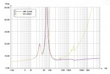
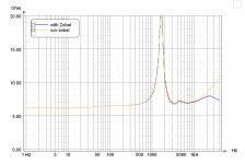
Those calculations are valid, and drastically reduce improve the impedance curve of the load. I have real life measurements of amplifier vs. load to confirm. If you calculate the Zobel with above formula u will see in real life that the impedance plot improve drastically. And u can even go further further with a extra second zobel network which improve things even more.
I design amplifiers for active speakers for many years, as well discrete as with chips in close relationship with the company who design their own drivers, so I have full access to the exact T/S parameters of the units. My above quotation is a simplistic way to calculate a reliable Zobel value for optimum interaction between amplifier and load. Like u can see in the below measurements for an active loudspeaker system in where I designed the amplifiers for, those calculations using above formula are very accurate and does make the loudspeaker unit attached a better load for the amplifier.
The chip manufacture never know the load the amplifier chip will see. And those loads are very variable. That is why I don't believe in a fixed value.
The LM1875 like to oscillate. I played around with those chips many years ago for a commercial product, and I am convinced in real life experience, that the manufacture specified Zobel doesn't always cut the cake.
Ps, attachment below is not a simulation but a measurement of a real existing product.
With kind regards,
Bas
Attachments
Last edited:
Hi Bas
Your getting confused and mixing things up.
There are Zobels for amps stabilty ie phase margin at HF above audio band, and then there's zobels for speakers at LF, they are not the same thing or application!! A zobel is a generic term really. Its just a frequency selective way of introducing a real resistance and canceling a reactive part.
In these chip amplifier threads we can talk about amp zobels. Please read Kevins reply to you in the thread post #12 and my link again in the other thread a couple of days ago. Thanks
Hi Bas
Your getting confused and mixing things up.
There are Zobels for amps stabilty ie phase margin at HF above audio band, and then there's zobels for speakers at LF, they are not the same thing or application!! A zobel is a generic term really. Its just a frequency selective way of introducing a real resistance and canceling a reactive part.
In these chip amplifier threads we can talk about amp zobels. Please read Kevins reply to you in the thread post #12 and my link again in the other thread a couple of days ago. Thanks
Dear Infinia,
I am not mixing things up. My point was and still is, you want the amp to be stabile with inductive and/or capacitive components in the load. Many amplifiers start to oscillate when the phase margin change due inductive or capacitive components in the load. If you take the manufactures Zobel network of 1 ohm/220n one can not guarantee that the amplifier is isolated from a highly inductive unknown load.
I have seen a LM1875's literally exploding adding the wrong zobel network (despite the promised protection circuits). When I talk about Zobel network in amplifiers, I mean the Thevin Thiele principe of how to tame a inductive/capacitive load. If your amplifier consist a high bandwidth with minimum compensation this is something u need to consider.
With kind regards,
Bas
Ps. Before I forgot. I took your advice and changed ceramic SMD's for film 1206 SMD caps in a DC servo. I tried the tapping test witht the scope. In both cases there was a case of a micro-phony effect with tapping. However when I change the capacitor for a film through-hole part this effect was reduced big time. So I guess I should not use SMD caps anymore in those critical applications. But strange enough even in very expensive "high end" equipment I have seen those ceramic capacitors in PLL loops
.
Last edited:
- Status
- This old topic is closed. If you want to reopen this topic, contact a moderator using the "Report Post" button.
- Home
- Amplifiers
- Chip Amps
- In memoriam LM1875T -- we had so lttle time