I would move the 100R resistors from the inputs to the outputs of the LME49600 to ensure that any difference in offset, current drive, etc. doesn't make the amps fight. You can probably reduce the resistors to 10R if you move them to the output. The resistors will raise the output impedance slightly, but it'll still be very, very low due to the global negative feedback.
But, honestly, I don't see the point of running multiple LME49600's in parallel for a headphone amp. They can deliver upwards of 500 mA short circuit current. For my headphone amp (driving a pair of Sennheiser HD-600's) I implemented the circuit in Figure 4 of the LME49600 Data Sheet. I chose to use the DC servo to set the LF pole.
Anyway... To your question: I'd use any electrolytic or tantalum cap that has low ESR and decouple it with a good polypropylene film cap for the supply caps in your circuit. The opamp will need separate 100 nF polyprop decoupling.
~Tom
Hello, I want to build headphone amp as per schematic. What kind of electrolytic caps should i use? audio grade, low esr, low impedance? any help would be greatly appreciated.
Dear Dr. Popo,
Nice idea!
")
Some comments:
1: Make the 100K input resistor 20K, so that the positive leg sees the same impedance as the negative leg. This will reduce DC offset and destortion. A 20K input impedance is a good value in my opinion, unlike u feed it with high output impedance tubes.
2:Like Tom commented, put resistors (something in between 47R and 100R in series with the output. Else the output opamps will become really hot and can even get destroyed. Then take the feedback AFTER those output resistors to keep the output impedance low.
Good luck!
With kind regards,
Bas
Thanks to everybody! I will now look for low esr capacitors and start soldering. Does anybody have any suggestions as to how i should solder LME49600 to pc board? I am good at soldering but never have come across ic in power pad package!
Don't forget to change the 100K input resistor to ground for 20K or a equal of the feedback resistor. Also, are you not afraid to fry your headphone voice-coil in case of DC offset? I would add a DC servo to the system. (no input cap!
) If u find it hard to design a DC servo I am happy to help you with your application and do that part for you With kind regards,
Bas
Dear Bas, Many thanks for your reply. Any help would be greatly appreciated!
Dear Dr. Popo,
Hold on I will draw for you tonight. The reason why I like to do this is, is because I always liked te headphone amplifier concept with the diamond output buffers. Weather it is the Burrbrown Buff634 variant or the new National ones.
Is there a reason you didn't add a volume control?
With kind regards,
Bas
If u find it hard to design a DC servo I am happy to help you with your application and do that part for you.
Why not just follow the Figure 4 headphone amp circuit in the datasheet to begin with? It already includes a servo.
More buffers can be paralleled as needed.
Why not just follow the Figure 4 headphone amp circuit in the datasheet to begin with? It already includes a servo.
More buffers can be paralleled as needed.
Sorry, I didn't look at this sheet yet, I see it now. The difference is only that the OP choose a voltage gain of 20, and the circuit in this sheet has a voltage gain of 3. The servo design and the resistor values must be changed with a voltage gain of 20.
With kind regards,
Bas
EDIT: The circuit in the actually has a voltage gain of 3, since the 1K resistor to ground and the 1K resistor to the output of the opamp makes those seen as 500 ohm.
Last edited:
Sorry, I didn't look at this sheet yet, I see it now.
No problem, I was just confused as it seemed like that circuit was being intentionally disregarded here for some reason.
I've built it already and it performs very well. I can't imagine ever needing more than one buffer per channel for headphones though.
No problem, I was just confused as it seemed like that circuit was being intentionally disregarded here for some reason.
Oh no, I like the circuit from the sheet! A good designed servo with equal legs for both inputs from the servo input. One can never go wrong with this circuit and must sound good. If the OP can live with a gain of 3, I would highly recommend to copy/paste this circuit. If he want to stick with a voltage gain of 20, then some adjustments need to make to the servo circuit.
With kind regards,
Bas
Toto, I've a feeling we're not in Kansas any more. ...
I'm afraid some of the suggestions are past their "use by date" - when you're wrapping a 50+MHz GBW op amp's feedback loop around a 180 MHz buffer some of yesteryears app note and published headphone amp project topologies need modification
Headphone cable C can surprise you - 1 nF is not impossible even in the manufacturer's standard cable due to flexible cables putting the wires very close together - custom cables of exotic construction can be worse
Load C is a bigger problem as loop intercept frequencies rise - what mostly worked with 4-8 MHz GBW op amps may not with 6-10x faster parts
resistance in series with the output, inside the feedback loop is definitely a bad idea unless you know your load C and add some more parts to define a 2nd order filter function - and you'd want a 50+ MHz GBW oscilloscope to verify that you were successful
much smaller R after the feedback point, in series with the load, helps damp the reaction of cable load C with the complex (rising with frequency ~+ inductance) output impedance of feedback amplifiers; 10-25 Ohms if you don't mind the R in series with the headphone - or use lossy ferrite or parallel R,L like many SS audio power amps
series R at the input of the buffer can be good - the LME data sheet claims it is stable with any C load if terminated in 50 Ohms on the input
you need to rearrange the earlier suggested series R to be effective at much higher frequencies - as a RC "Zobel" to gnd instead
likewise toss out any "audiophile capacitor" nonsense for the ps bypass at the chips - you need ultra low parasitic inductance - use monolithic ceramic chip caps at the op amp, buffer supply pins - to a solid gnd plane - the "order of magnitude scaled parallel bypass caps" rule of thumb also should be looked at with suspicion - at these frequencies you can get resonant peaks between the SRF of the different type/value caps that can make ps worse rather than better
Last edited:
I'm afraid some of the suggestions are past their "use by date" - when you're wrapping a 50+MHz GBW op amp's feedback loop around a 180 MHz buffer some of yesteryears app note and published headphone amp project topologies need modification
Headphone cable C can surprise you - 1 nF is not impossible even in the manufacturer's standard cable due to flexible cables putting the wires very close together - custom cables of exotic construction can be worse
Load C is a bigger problem as loop intercept frequencies rise - what mostly worked with 4-8 MHz GBW op amps may not with 6-10x faster parts
resistance in series with the output, inside the feedback loop is definitely a bad idea unless you know your load C and add some more parts to define a 2nd order filter function - and you'd want a 50+ MHz GBW oscilloscope to verify that you were successful
much smaller R after the feedback point, in series with the load, helps damp the reaction of cable load C with the complex (rising with frequency ~+ inductance) output impedance of feedback amplifiers; 10-25 Ohms if you don't mind the R in series with the headphone - or use lossy ferrite or parallel R,L like many SS audio power amps
series R at the input of the buffer can be good - the LME data sheet claims it is stable with any C load if terminated in 50 Ohms on the input
you need to rearrange the earlier suggested series R to be effective at much higher frequencies - as a RC "Zobel" to gnd instead
likewise toss out any "audiophile capacitor" nonsense for the ps bypass at the chips - you need ultra low parasitic inductance - use monolithic ceramic chip caps at the op amp, buffer supply pins - to a solid gnd plane - the "order of magnitude scaled parallel bypass caps" rule of thumb also should be looked at with suspicion - at these frequencies you can get resonant peaks between the SRF of the different type/value caps that can make ps worse rather than better
Oeps. I am not familiar with those opamps, and I didn't know they have such a high band-with open-loop gain. In that case it would't be a bad idea to compensate the design a little by simply adding a small capacitor from the drivers opamp output to the negative input to reduce the slew-rate and bandwidth to more a more safe zone.
With kind regards,
Bas
Is all of that really necessary though?
I don't have a scope, but the board I built has zero instability problems that I can tell. I've driven multiple different headphones and even small speakers with it and it never misbehaves.
I'm not an expert with this stuff, but I do know that reality is sometimes very different than simulations and assumptions.
you do have some added stability margin with a high amplifier gain of 10 - but your loop intercept frequency is ~ 5 MHz - higher than most discrete power amps - including most Mosfet output designs, so you should be prepared for similar problems - many "diy safe" project amps have loop intercept frequency below 500 KHz -as you would in a op amp project with a older 4-8 MHz GBW op amp
feedback circuits can "work", giving "acceptable" audio even while oscillating, possibly at a level that doesn’t heat the chips too much
you really can't be sure of a design unless you’ve looked at it with a 'scope faster than the fastest device in the feedback loop - look for Bob Pease comments on practical stability testing and Linear Technology's High Speed Op Amp design app notes
R in series with the output, inside the feedback loop, reacting with load C is accurately modeled - 100 Ohms * 1 nF ~= 1.6 MHz, you would be adding >70 degrees phase shift to the loop at 5 MHz => over 2x overshoot (armchair guestimate - it can be calculated/simmed to as much accuracy as you know the op amp GBW at those frequencies)
the local feedback C around the input op amp does slow the loop and can tune the damping of the Cload overshoot - but it continues the feedback of the op amp to unity gain at 50 MhZ - requiring good ps bypass performance to beyond that frequency
you may not need to apply every high speed design trick for some instances of these circuits to work - but you are walking near the edge and may not realize when a "simple" change takes you over into high speed instability
Last edited:
Dear,
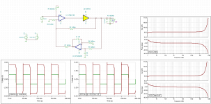
For fun I made some quick simulation. I don't have Spice models from this national devices, but I used the OPA637/Buf634 instead. The Buf634 is in specs exactually equal to the LME49600. The Opa637 comes close to the LME49720.
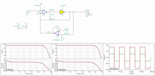
This simulations are not the real world and this parts are not equal, but you can be sure with such a high open-loop bandwidth that the situation with this headphone amp comes close, or worser. Simulated is first the schematic from national, with 100 ohm load, and 100Ohm/1nF load. The second attachment I compensated the circuit slightly with 47pF as can be seen in the schematic. For my taste still a to big bandwidth to almost MHz! I would even limit it further.
Personally I would change the circuit and add a lowpass filter at the input (but resistor values have to change then in order to make it work).
The original circuit is working on the edge of oscillation I fear.
With kind regards,
Bas
For fun I made some quick simulation. I don't have Spice models from this national devices, but I used the OPA637/Buf634 instead. The Buf634 is in specs exactually equal to the LME49600. The Opa637 comes close to the LME49720.
This simulations are not the real world and this parts are not equal, but you can be sure with such a high open-loop bandwidth that the situation with this headphone amp comes close, or worser. Simulated is first the schematic from national, with 100 ohm load, and 100Ohm/1nF load. The second attachment I compensated the circuit slightly with 47pF as can be seen in the schematic. For my taste still a to big bandwidth to almost MHz! I would even limit it further.
Personally I would change the circuit and add a lowpass filter at the input (but resistor values have to change then in order to make it work).
The original circuit is working on the edge of oscillation I fear.
With kind regards,
Bas
Attachments
I would like to add, that working with a bigger voltage gain would improve things drastically, and this is in the benefit of the OP who wanted to work with a voltage gain of 20. However I wonder if that is not way to much gain with modern sources to feed a headphone.
With kind regards,
Bas
With kind regards,
Bas
Does anybody have any suggestions as to how i should solder LME49600 to pc board? I am good at soldering but never have come across ic in power pad package!
How To Solder Surface Mount Devices & Chips With Solder Paste & Hot Air. SMD Soldering! I made a setup similar to this and I use a micro butane torch instead of a hot air pencil, a halogen spot on the under side with a dimmer for preheat.
- Status
- This old topic is closed. If you want to reopen this topic, contact a moderator using the "Report Post" button.
- Home
- Amplifiers
- Chip Amps
- Lme49600 headphone amp