hi
i got a old 5.1 home theatre system and i wanna recycle it into a 2.1 PC speaker set.
well i took it apart and found that it has 5x TDA2003 and 1x TDA2030A and couple 7805, 7812 regulators a toroidal transformer and loads of capacitors and resistors loads of other stuff.
also one 6" woofer and 5 small speakers.
so i was looking up the schematics on the amplifiers and found that they could easily be used for a 2.1 speaker setup
so i was thinking that i could use 4 Tda2003's, 2 bridged for left and 2 bridged for right and the Tda2030a for the woofer.
i just need help connecting it up with the power and how to have the woofer for the bass.
thanks
Attachments
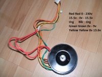
The transformer voltages are measured values with no load connected?
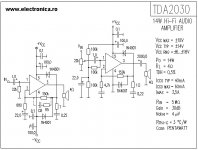
The TDA2030A was probably hooked up to the 15,5-0-15,5 V in split supply configuration, so you will need a different schematic (Figure 14 from the datasheet?)
The TDA2003 were probably connected to the 13,6 V winding.
Do you want to bridge the TDA2003s just because you have enough of them or is there any other reason for it?
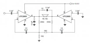
That bridged schematic will not work. The right amp does not get an inverted signal, the left amp needs a virtual ground and connecting the two feedback signals through a 16 Ohm resistors does not look promising either.
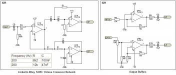
You will need a crossover before the amplifiers. You can see a passive version in the TDA2030As datasheet. The size of the 5 small speakers and their T/S parameters will more or less determine the crossover frequency and steepness.
The TDA2030A was probably hooked up to the 15,5-0-15,5 V in split supply configuration, so you will need a different schematic (Figure 14 from the datasheet?)
The TDA2003 were probably connected to the 13,6 V winding.
Do you want to bridge the TDA2003s just because you have enough of them or is there any other reason for it?
That bridged schematic will not work. The right amp does not get an inverted signal, the left amp needs a virtual ground and connecting the two feedback signals through a 16 Ohm resistors does not look promising either.
You will need a crossover before the amplifiers. You can see a passive version in the TDA2030As datasheet. The size of the 5 small speakers and their T/S parameters will more or less determine the crossover frequency and steepness.
i found a schematic for the tda2003, but i really wanted to use two amp to drive two speakers in parallel but its not going to work cause of the output voltage.
maybe go for the tda7240a amp chip which is a bridged
the transformer voltages are on the side not sure what they would be after a bridge rectifier.
maybe go for the tda7240a amp chip which is a bridged
the transformer voltages are on the side not sure what they would be after a bridge rectifier.
I looked up bridge cirucuits with the TDA2003, and found one similar and this circuit in the UTC2003 data sheets. The DC voltages are internally set in the 2003, and the circuit uses the voltage at the node where the 2 16 ohm resistors meet (Which should be the same as the input voltage) to drive the second amp as an inverting amp. However, I find the 7240 and the 2030 are better sounding amps than the 2003. My 2 cents. (At first I thought the circuit wouldn't work either, but decided it would after doing some research and thinking it through.)
Last edited:
When you use speakers in parallel the limiting factor will rather be the current than the voltage. You could also use one amp per speaker just like it was before.but i really wanted to use two amp to drive two speakers in parallel but its not going to work cause of the output voltage.
~1,41 times the values you measured minus the voltage drop across the rectifier, minus the voltage sag when a load is present.the transformer voltages are on the side not sure what they would be after a bridge rectifier.
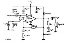
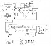
this is want im doing im going to use 2x tda7240 and the tda2030.
and ive got these schematic so far
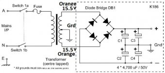
going to use 15.5v on the 7240's and the 13.6v on the 2030. which i dont know which wire goes where. dont really understand transformers wiring.
but ive tried with the pic if thats right with 15.5v, if so i will use the same for the 13.6v.
i have a 2w10m bridge rectifier but i cant seem to find the voltage drop in the datasheet.
and i have diodes from 4001- 5401
and ive got these schematic so far
going to use 15.5v on the 7240's and the 13.6v on the 2030. which i dont know which wire goes where. dont really understand transformers wiring.
but ive tried with the pic if thats right with 15.5v, if so i will use the same for the 13.6v.
i have a 2w10m bridge rectifier but i cant seem to find the voltage drop in the datasheet.
and i have diodes from 4001- 5401
Attachments
- Status
- This old topic is closed. If you want to reopen this topic, contact a moderator using the "Report Post" button.
- Home
- Amplifiers
- Chip Amps
- diy 2.1 pc speakers