Hello!
This is my first post in this forum, and the first thing I want to say is... A Big Thanks! My first DIY audio project would not be possible without the ideas and resources provided by the users on this site") (and Tangentsoft site too!).
(and Tangentsoft site too!).
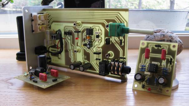
This is my custom CMoy Test Board.
Power Section:
1 x Panasonic FC 470uF 25V Electrolythic Capacitor.
1 x Texas Instruments TLE2426CP Rail Splitter.
1 x DIP8 Socket.
1 x Generic 1uF 63V Polyester Capacitor (TLE noise reduction).
3 x Molex KK 2 pin Vertical Male Connectors (power input connector, power switch connector and led connector).
Op-Amp Section:
2 x Matsushita/Panasonic Metallized Polyester Film Capacitor ECQE Series - 0,1uF/100V - (Mylar PET Dielectric) (input capacitors).
1 x Texas Instruments / Burr-Brown OPA2134PA Op-Amp.
2 x Generic 0,1uF 100V Polyester Capacitor (Op-Amp decoupling capacitors).
1 x DIP8 Socket.
2 x Molex KK 3 pin Vertical Male Connectors (audio input / output connectors).
2 x Generic 100K 1/4W Resistor.
2 x Generic 10K 1/4W Resistor.
2 x Generic 2,2K 1/4W Resistor.
Other components:
1 x M223-RS 6,5mm. Female Switched Stereo Connector (chassis mount) (audio output jack).
1 x Generic 3,5mm. Female Stereo Connector (chassis mount) (audio input jack).
1 x Vishay P9A Series 100mW 10K Logarithmic Dual Potentiometer (chassis mount) (audio input attenuation).
1 x Generic 5mm. Red LED.
1 x Generic 5mm. LED Holder (chassis mount).
1 x Generic 100K 1/4W Resistor (LED resistor).
1 x Generic Switch (chassis mount).
1 x Generic Power Socket (chassis mount).
3 x Molex KK 2 pin Female Connectors (power input jack, power switch and led holder).
2 x Molex KK 3 pin Female Connectors (audio input / output jacks).
1 x Generic 12V 1.25A Wall Wart (power supply).
Components to test:
2 x Vishay Metallized Polyester Film Capacitor MKT Axial Type - 0,47uF/63V (PLYE Dielectric) (input capacitors replacement).
1 x Vishay P9A Series 100mW 50K Logarithmic Dual Potentiometer (chassis mount) (audio input attenuation replacement).
Some photos:
This is my first post in this forum, and the first thing I want to say is... A Big Thanks! My first DIY audio project would not be possible without the ideas and resources provided by the users on this site
(and Tangentsoft site too!).This is my custom CMoy Test Board.
Power Section:
1 x Panasonic FC 470uF 25V Electrolythic Capacitor.
1 x Texas Instruments TLE2426CP Rail Splitter.
1 x DIP8 Socket.
1 x Generic 1uF 63V Polyester Capacitor (TLE noise reduction).
3 x Molex KK 2 pin Vertical Male Connectors (power input connector, power switch connector and led connector).
Op-Amp Section:
2 x Matsushita/Panasonic Metallized Polyester Film Capacitor ECQE Series - 0,1uF/100V - (Mylar PET Dielectric) (input capacitors).
1 x Texas Instruments / Burr-Brown OPA2134PA Op-Amp.
2 x Generic 0,1uF 100V Polyester Capacitor (Op-Amp decoupling capacitors).
1 x DIP8 Socket.
2 x Molex KK 3 pin Vertical Male Connectors (audio input / output connectors).
2 x Generic 100K 1/4W Resistor.
2 x Generic 10K 1/4W Resistor.
2 x Generic 2,2K 1/4W Resistor.
Other components:
1 x M223-RS 6,5mm. Female Switched Stereo Connector (chassis mount) (audio output jack).
1 x Generic 3,5mm. Female Stereo Connector (chassis mount) (audio input jack).
1 x Vishay P9A Series 100mW 10K Logarithmic Dual Potentiometer (chassis mount) (audio input attenuation).
1 x Generic 5mm. Red LED.
1 x Generic 5mm. LED Holder (chassis mount).
1 x Generic 100K 1/4W Resistor (LED resistor).
1 x Generic Switch (chassis mount).
1 x Generic Power Socket (chassis mount).
3 x Molex KK 2 pin Female Connectors (power input jack, power switch and led holder).
2 x Molex KK 3 pin Female Connectors (audio input / output jacks).
1 x Generic 12V 1.25A Wall Wart (power supply).
Components to test:
2 x Vishay Metallized Polyester Film Capacitor MKT Axial Type - 0,47uF/63V (PLYE Dielectric) (input capacitors replacement).
1 x Vishay P9A Series 100mW 50K Logarithmic Dual Potentiometer (chassis mount) (audio input attenuation replacement).
Some photos:
An externally hosted image should be here but it was not working when we last tested it.
An externally hosted image should be here but it was not working when we last tested it.
An externally hosted image should be here but it was not working when we last tested it.
An externally hosted image should be here but it was not working when we last tested it.
An externally hosted image should be here but it was not working when we last tested it.
An externally hosted image should be here but it was not working when we last tested it.
An externally hosted image should be here but it was not working when we last tested it.
An externally hosted image should be here but it was not working when we last tested it.
An externally hosted image should be here but it was not working when we last tested it.
An externally hosted image should be here but it was not working when we last tested it.
An externally hosted image should be here but it was not working when we last tested it.
An externally hosted image should be here but it was not working when we last tested it.
An externally hosted image should be here but it was not working when we last tested it.
isen78, that's awesome! And the pitcures are great too. I often forget to setup clean "studio" space up for pictures. Glad you did.
Question for you, am perhaps I'm not understanding something. But it seems that you built this test board to test 2 parts?
I really like the styro/paper layout idea and shots.
Also, you've got to tell us how it sounds.
jugtree
Question for you, am perhaps I'm not understanding something. But it seems that you built this test board to test 2 parts?
I really like the styro/paper layout idea and shots.
Also, you've got to tell us how it sounds.
jugtree
Thanks!
I´ve done some circuits before, but this is my first home-etched PCB and my first audio project. And I´m very happy with it! Sounds great using my iPod Touch or iAudio M5 line out (using standard stereo jack output sounds great too). I don´t have cutting-edge headphones... but now, my Sony MDR-V250 or Sennheiser HD-555 seems to sound a lot of better than before.
Jugtree, I want to test the whole circuit in only one part, putting the rail splitter and the opamp on the same pcb and see how it sounds. Maybe I´m missing your point... My english is far from perfect
Isen.
Some tweaking...
I´ve just finished testing a few changes that I´ve done to the board.
2.2K Resistors have been replaced by 1.2K resistors. CMoy´s gain is now (10/1.2)+1=9,3dB and has better volume using ipod/iaudio standard stereo jack.
Panasonic ECQE 0,1uF/100V input capacitors have been replaced by Vishay MKT 0,47uF/63V capacitors. Much better bass handling!!! My Sennheiser HD555 headphones sound incredible to me.
10K 1/4W LED resistor has been replaced by 4.7K 1/4W resistor. Brighter LED
Some Photos:
An externally hosted image should be here but it was not working when we last tested it.
An externally hosted image should be here but it was not working when we last tested it.
Let those Big Red Caps roll!
New WIMA MKP10 0.47uF 400V caps. Better sound in general and slightly better bass response...
Photos:
New WIMA MKP10 0.47uF 400V caps. Better sound in general and slightly better bass response...
Photos:
An externally hosted image should be here but it was not working when we last tested it.
An externally hosted image should be here but it was not working when we last tested it.
isen78 very nice work nice also that you take pride in your pictures
heres one i put together my self into a Hammond i also included alot of options inc plug in modules
you can read more on it here Project | Homebuilt Hi-Fi - A user submitted image showcase of high quality home built hi-fi components.
Best Regards
Koogar
heres one i put together my self into a Hammond i also included alot of options inc plug in modules
you can read more on it here Project | Homebuilt Hi-Fi - A user submitted image showcase of high quality home built hi-fi components.
Best Regards
Koogar
- Status
- This old topic is closed. If you want to reopen this topic, contact a moderator using the "Report Post" button.
- Home
- Amplifiers
- Chip Amps
- My First DIY Audio Project: A Custom CMoy Test Board.