Hi guys, I noticed this for sale on ebay and was wondering if anybody may be able to fill me in on some specs for it
New - 300W LME49810 Mono channel Audio Amplifier Board - eBay Amplifiers, Audio, Video, Car Parts, Accessories, Cars, Bikes, Boats. (end time 15-Apr-10 05:13:34 AEST)
I would like to know what impedance it is meant to run at and what it could drive (ie lower impedances such as 2 ohms) if the supply voltage was lowered and if other circuit mods would be required to do so.
Cheers, Junglejuice
Attachments
Yeah I have that, so how using the above circuit determine what the power would be @ 4 ohms or 2 ohms?
The math is simply. Output power (RMS) will be about (supply voltage minus min. Vce for linear operation)/(2*Load), Load = 2, 4, 8 Ohm etc.
The supply is +/- 45 VDC. For 4 Ohm, you will get around (40*40)/(2*4) = 200 W (assume min Vce = 5 V).
Ok that makes sense, on the board it has 300w listed so using the formula above for a 2 ohm load would 400w, is this too much for these transistors to handle or do I need to lower the supply voltage to 40v to give an output of 300w @ 2 ohms? 400w @ 2 ohms would be better though....
Cheers
Cheers
here is some extra reading on this subject.
http://www.diyaudio.com/forums/solid-state/155173-anyone-recognise-design-based-lme49810.html
http://www.diyaudio.com/forums/solid-state/155173-anyone-recognise-design-based-lme49810.html
expect the output transistors to have a dissipation capacity very approximately equal to 4times the maximum output power, i.e. 300W of maximum output power requires ~1200W of devices, 400W requires ~1600W of devices.on the board it has 300w listed so using the formula above for a 2 ohm load would 400w, is this too much for these transistors to handle or do I need to lower the supply voltage to 40v to give an output of 300w @ 2 ohms? 400w @ 2 ohms would be better though....
expect the output transistors to have a dissipation capacity very approximately equal to 4times the maximum output power, i.e. 300W of maximum output power requires ~1200W of devices, 400W requires ~1600W of devices.
That seems to be a bit excessive to me, I was under the impression most amps run at about 50% efficiency including power supply so that would mean @ 400w the amp and supply would draw 800w, correct me if I am wrong.....
eg.
take a pair of 130W output devices. That's a total of 260W.
Divide by 4. This results in an estimate of maximum output power of approximately 65W.
Determine what load you intend to use. Let's make that 8ohm for this example.
Determine as a first guess the supply rails for 65W into 8r0.
Vrms = sqrt( max power * load resistance) = 22.8Vac
Vpk = sqrt( max power * load resistance * 2) = 32.2Vpk.
Allow about 6V for losses and PSU sag under full power.
You need ~+-38.2Vdc to get 65W into 8r0 from one pair of 130W devices.
This should be able to drive a real 8ohm speaker reliably if normal sized transformer and normal sized smoothing capacitance and normal sized heatsink are all used.
This will not drive a 4ohm speaker. That original set of assumptions applied to an 8ohm load.
If you had 2pair of 250W devices (total 1kW) and a 4ohm load, go through the same process and determine first guess for maximum output power and PSU requirement.
Last edited:
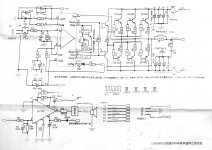
The thing that bothers me about this board is that the photograph of the board doesn't match the downloaded diagram.
The diagram shows 3 pairs of 2SC5200 and 2SA1943 transistors whereas the photo shows 5 pairs.
The transistors are rated at 15A max and 150W dissipation, so about 75A and 1500W total, collectively.
Given the power factor divisor of 4, then the board should be capable of dissipating 375W.
The problems arise when you want to drive the board into low impedance loads.
If you wanted to run this power into 2R, then your maximum rail voltage would be 38.7v and peak current of 19.35A to top out the power at 375W.
The output transistors would supply that current easily but the limited rail voltage would give a maximum power into 8R of only 93.6W
It's all swings and roundabouts, I'm afraid.
Sandy
at least you can admit it. Most refuse to believe there are ways to find the answer and plod on regardless.i don't understand
Download Bensen's spreadsheet or look at the many other SOAR calculators in this Forum to learn why that factor of ~4 becomes necessary, rather than simply saying "it can't be".
i dont understand why the giant safety factor when power dissipation can be calculated w/o a lot of hustle. all the data is in the dsheet..
It is indeed but the question is, "how are YOU interpreting the data"?
If you're assuming that the output transistors can dissipate 150W each and that's an end of it, then you're going to have some interesting smoke effects from your amplifiers.
")
Have a look here;
http://akizukidenshi.com/download/2SC5200.pdf
and go down to the Safe Operating Area (SOA) plot.
The main things to understand is that highest power is obtained with very short pulses and ONLY if the Collector junction is kept at 25 deg C.
The first has virtually no place in the real world of audio signals and unless you have a refrigerated coolant system, the 25C junction temperature is not feasible with any decent power going through the transistors.
Unfortunately, in the real world, you might very well wish to go down to DC and this brings serious consequences.
The board from Ebay only has a + or - 65v rail, and maximum transistor dissipation happens when the conducting transistor is at half rail voltage, i.e. 32.5v and fron the SOA plot, this will give a MAXIMUM current per device of about 4.5A and thus a maximum dissipation of 150W
Looks good, so far, doesn't it but if your junction temperature goes up to 100C (not outside the realms of possibility), the dissipation drops immediately to 62.5W per device. Obviously, this will get worse, the hotter the junction gets.
In fact, you just have to go up another 18C, to 118C and you're down to 37.5W, i.e. 1/4 dissipation.
The simple fact is that unless you have MASSIVE heat sinking capability, standard bipolar transistors MUST be run very conservatively or they will blow up with monotonous regularity.
Sandy
SOA and temperature de-rating applies equally to BJT and FET output stages, not just BJT.
Quite correct but as the thread concerns the LM49810 on Ebay and THAT board uses BJT's, I disregarded FETs. I was simply attempting to explain the reasoning for the "apparently" high over specification of the output stage.
And always remember that a speaker is an reactive load, not a pure resistive load.
Irrelevant in the spirit of the thread, as amplifiers should always be rated into a purely resistive load to maintain consistency in measurements.
Sandy
andrewT,
you wrote:
"If the load is reactive then the current can be out of phase with the voltage and now Vds can be high and output current can be medium, but the dissipated power can be very high. This is the condition that really stresses the FET's SOAR"
is this the root of all evil here?
is my mistake looking at average dissipation figures derived from minimum efficiancy?
isnt this figure (~4) dependant on heatsink&contact thermal resistance?
i appologize for asking rather than searching, but this forum holds masive amounts of data. i get lost here more often then not.
thanks
mnemneth, is it possible you are confusing case temp with junction temp?
please, some credit here...when i said the data is in the dsheet i didnt mean just take max Pd. there is a lot more dissipation data there: thermal resistances and max Tj is what i used, apparently naively so, as i use the steady state numbers derived from 50% eff (dissipate the same as the speakers see).
if i understand you and andrewt correctly, you use max instantaneous Pd?
- Status
- This old topic is closed. If you want to reopen this topic, contact a moderator using the "Report Post" button.
- Home
- Amplifiers
- Chip Amps
- LME49810 on ebay