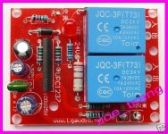
Has anyone any experience with these boards?
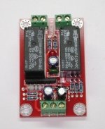
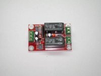
I picked up a couple of these reasonably cheap from ebay seller zoe_tsang. He sent the following connection diagram which I do not really understand. He says he doesn't have a schematic (typical of Chinese sellers) but ignored a request in the same email to clarify the connections.
(I know, buyer beware of buying from China on Ebay but they were cheap so not much is lost other than experimenting time.)
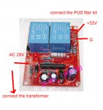
The second picture is of the connection diagram the seller sent after I bought it last year.
I picked up a couple of these reasonably cheap from ebay seller zoe_tsang. He sent the following connection diagram which I do not really understand. He says he doesn't have a schematic (typical of Chinese sellers) but ignored a request in the same email to clarify the connections.
(I know, buyer beware of buying from China on Ebay but they were cheap so not much is lost other than experimenting time.)
The second picture is of the connection diagram the seller sent after I bought it last year.
Attachments
Last edited:
Have you looked at the data sheet for typical application ?
http://www.datasheetcatalog.org/datasheet/nec/UPC1237.pdf
It needs a supply ! which will feed into the diode as marked. The diode means you can feed either AC or DC into the PCB.
Identifiy the ground connection.
Identifiy the inputs from the amplifier.
Identifiy the relay connections.
Easy 🙂
http://www.datasheetcatalog.org/datasheet/nec/UPC1237.pdf
It needs a supply ! which will feed into the diode as marked. The diode means you can feed either AC or DC into the PCB.
Identifiy the ground connection.
Identifiy the inputs from the amplifier.
Identifiy the relay connections.
Easy 🙂
Thanks Mooly and kavermei;
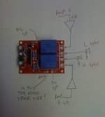
(Apologies for the camera phone pictures below - not always clear with closeups).
The boards I have are labeled in English. The relay speaker connection side is clear and connections per the diagram I drew.
The +32V VCC+ (as labeled) connection is clear as is the GND, assuming one wanted to use DC to power the board.
There is an "AC 28" hole which connects to the transformer. What about the other side of the transformer? Where does it connect to? if it is the "GND" point, it doesn't work, the relays are open.
I'm not normally this blind to this, I do have some electronics experience but either the board is faulty (which I am doubting) or I am missing something.
I do have the datasheet and at first glance it wasn't helpful.
Attachments
Last edited:
It's hard to tell for sure without a schematic. If you could trace out the circuit diagram from the PCB traces, I'm sure we could tell you in a second.
kavermei:
My point precisely which is why I asked for a schematic. Lots of these boards are being flogged by several sellers and I thought perhaps someone on diyAudio might have come across it.
I'll attempt to trace it. It is double sided with some of the traces underneath the relays which I'll pull out if need be. At that point I should be able to figure it out and post it here for the diyAudio community for reference.
Hi,
it is likely that the AC in is a detect loss of AC and disconnect speakers.
The PCB is likely to be powered by the two adjacent pads using DC.
it is likely that the AC in is a detect loss of AC and disconnect speakers.
The PCB is likely to be powered by the two adjacent pads using DC.
Hi,
it is likely that the AC in is a detect loss of AC and disconnect speakers.
The PCB is likely to be powered by the two adjacent pads using DC.
Yes, that is quite likely, the purpose being to avoid the 'thump' in the speakers at power-off.
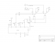
OK, so I've traced the circuit. It is virtually identical to the datasheet's typical application schematic. Very minor changes. I've redrawn it to make more sense. The amp L and R channel outputs are sampled by the two 56K resistors connected to UPC1237's pin 2. Any DC there and the relays open I guess.
Also, I think Andrew T and kavermei are correct, the AC connection detects loss of AC. Question remains, what is the other side of the winding connected to? It may not be (and isn't in my case) the PSU circuit ground.
The board is powered by VCC+/GND, not that or AC IN as I originally thought.
So, the schematic is attached for diyAudio community's reference.
Attachments
Last edited:
Yes, this confirms it.
It's not important whether the other side of the winding is connected to GND or not. What matters is that some voltage can be measured between the 'AC' terminal and GND, and that that voltage disappears when the amp is shut off. Just connect it to any secondary terminal on the main transformer, or connect it to VCC if you don't need the functionality.
It's not important whether the other side of the winding is connected to GND or not. What matters is that some voltage can be measured between the 'AC' terminal and GND, and that that voltage disappears when the amp is shut off. Just connect it to any secondary terminal on the main transformer, or connect it to VCC if you don't need the functionality.
I am using one of those and they work pretty good. The AC pad is just there to immediately disconnect the speakers on power off. It'll eliminate thumps on power off, if you've got any. It needs to have a voltage difference with GND for the circuit to work, so you've got to connect it either to the AC from your transformer, or your VCC. The voltages specified on the board are not critical, you can have different values, but check the datasheet for the 1237 to determine your ranges. If you need to use other values, you just need to change a resistor, so it's pretty versatile.
I've ran pretty stressing tests, because I was paranoid about speaker safety in my first build. It works perfectly.
I've ran pretty stressing tests, because I was paranoid about speaker safety in my first build. It works perfectly.
Thanks Atilla. I got a good understanding of the board once I traced the circuit. Thanks for your input as to its worthiness.
So where does the other side of the transformer goes? GRND? and any thoughts how to wire it for stand alone module?
I bought one of these boards the other day too, and had similar experiences with the lack of information from the supplier. From your discussions, am I correct in understanding that the board can be powered through EITHER the AC 26V OR the VCC + terminals? My next question relates to my use of this circiut - I want to protect my subwoofer, so can I just use one channel on this pcb? I'm driving the subwoofer from a bridged TDA7294 cofiguration, will this affect the operation of the protection circuit?
The best reference for this is to use the UPC1237 datasheet.
The board is powered from the VCC+, but it is also designed to detect loss of AC power , so it has another reference input, for which you could use the VCC+ as well, if you don't want to use that function.
You can use it for one channel only, without problem. Just don't connect anything to the second input/output pair.
The "+32V" is your positive rail, the "-" is GND, "AC" is meant to be taken from the transformer, so it immediately disconnects the speakers when it senses the power is off, rather than waiting for the caps to discharge.
Last edited:
Just to update this thread, for what it's worth, there is a new "YJ" version currently on ebay. It looks very similar with the layout changed to accommodate different form factor relays (I assume). Anyway, just as my schematic in post #10 of this thread shows, this one is not likely to vary from the upc1237 data sheet by much.
The link to the ebay listing: BTL Speaker protected board-yj on eBay.ca (item 190506327839 end time 05-Mar-11 10:32:16 EST)
Below are 2 photos and (can you believe it!) a connection diagram!
The link to the ebay listing: BTL Speaker protected board-yj on eBay.ca (item 190506327839 end time 05-Mar-11 10:32:16 EST)
Below are 2 photos and (can you believe it!) a connection diagram!
Attachments

Last edited:
I kind of avoid some of the eBay designs, the "YJ" looks too cheap...
Just noticing the use of 12V relays with power from rectified AC 22V-32V, or 30-44VDC... which is crazy even if the relay coils are in series. Gone is the bi-polar input cap too.
Just noticing the use of 12V relays with power from rectified AC 22V-32V, or 30-44VDC... which is crazy even if the relay coils are in series. Gone is the bi-polar input cap too.
Interesting that TheLaw117 has the same question regarding the 12vdc relays in post # 309 here: http://www.diyaudio.com/forums/chip...e-3886-ebay-amazing-value-31.html#post2485541
this is not crazy.Just noticing the use of 12V relays with power from rectified AC 22V-32V, or 30-44VDC... which is crazy even if the relay coils are in series.
Two 12V relays would expect 24Vdc to operate reliably. The excess voltage of 6V to 20V is dropped across a resistor selected to suit the Vac that the builder chooses.
- Status
- Not open for further replies.
- Home
- Amplifiers
- Chip Amps
- Speaker Protection board from Ebay