I made two parallel TDA7293 amp boards for driving bass drivers in my active 2-way system and the boards are working perfectly so I thought it would be good to share my project with the community. Maybe someone finds it useful.
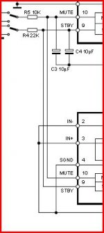
My schematic is almost the same as in datasheet, except for some minor changes in component values. I increased the bootstrap capacitor to 68uF, and the feedback and input resistors to 88,7k / 2,7k. I meant to use 82k, but 88,7k was what I had at home so that's what I used. Slightly higher gain and probably noise, but amp is still dead silent even with my ear pressed to the speaker cone so I don't worry.
Pinout on TDA7293 is made by madman so single-sided board is difficult to draw, and in the end contains more jumpers between lines than lines . Once I made single-layer board for TDA's and it was a nightmare. So this one is made double sided.
I don't use pin5 clipping indicator because I don't need it and the mute/standby functions are connected directly to +Vs via resistor and capacitor just to provide protection from turn-on transients.
Finally I can get rid of my LM3886 amps. My old love TDA7293 sounds much sweeter to me
My schematic is almost the same as in datasheet, except for some minor changes in component values. I increased the bootstrap capacitor to 68uF, and the feedback and input resistors to 88,7k / 2,7k. I meant to use 82k, but 88,7k was what I had at home so that's what I used. Slightly higher gain and probably noise, but amp is still dead silent even with my ear pressed to the speaker cone so I don't worry.
Pinout on TDA7293 is made by madman so single-sided board is difficult to draw, and in the end contains more jumpers between lines than lines
. Once I made single-layer board for TDA's and it was a nightmare. So this one is made double sided.I don't use pin5 clipping indicator because I don't need it and the mute/standby functions are connected directly to +Vs via resistor and capacitor just to provide protection from turn-on transients.
Finally I can get rid of my LM3886 amps. My old love TDA7293 sounds much sweeter to me
Attachments

Help with boards
I have been looking for a source of PCBs using parallel TDA7293s. There are not many out there that you can buy. I am not experienced in PCD design or I would try to make some myself.
Any chance of you making a batch of these and selling them?
-Charlie
I made two parallel TDA7293 amp boards for driving bass drivers in my active 2-way system and the boards are working perfectly so I thought it would be good to share my project with the community. Maybe someone finds it useful.
My schematic is almost the same as in datasheet, except for some minor changes in component values. I increased the bootstrap capacitor to 68uF, and the feedback and input resistors to 88,7k / 2,7k. I meant to use 82k, but 88,7k was what I had at home so that's what I used. Slightly higher gain and probably noise, but amp is still dead silent even with my ear pressed to the speaker cone so I don't worry.
Pinout on TDA7293 is made by madman so single-sided board is difficult to draw, and in the end contains more jumpers between lines than lines
I don't use pin5 clipping indicator because I don't need it and the mute/standby functions are connected directly to +Vs via resistor and capacitor just to provide protection from turn-on transients.
Finally I can get rid of my LM3886 amps. My old love TDA7293 sounds much sweeter to me
I have been looking for a source of PCBs using parallel TDA7293s. There are not many out there that you can buy. I am not experienced in PCD design or I would try to make some myself.
Any chance of you making a batch of these and selling them?
-Charlie
The TDA7293 is an interesting device... one I intend evaluating at some point.
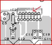
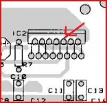
Cro maniac... pin 10 (the mute pin) on my data sheet shows the pins for master and slave connected, but the PCB appears to show pin 10 floating on the slave.
Cro maniac... pin 10 (the mute pin) on my data sheet shows the pins for master and slave connected, but the PCB appears to show pin 10 floating on the slave.
Attachments
Charlie, I don't mind making few boards by myself, but those won't look nearly as good as the ones made by proffesionals. Mine sometimes have miniature dots and pits on copper. And the thinner lines tend to be uneven.
I could also ask local manufacturer for price if more people want those boards.
Praudio, at +/-40V supply output power would be about 150W @4 ohms at the onset of clipping.
Yes Mooly, the board pics in the datasheet are flawed. I used them only as a guidance with component arrangement on my PCB after few futile attempts to route the board with minimum jumper count by myself.
You should be looking at the schematic which is correct.
There are even some minor differences in schematic of modular application between older and newer datasheets. Older ones had inputs of slave chip connected to signal ground, and the newer have them connected to -Vs which is how I did it.
By bass in two way speaker I meant bass-midrange driver, not subwoofer.
I like the sound of TDA's, and the design with LME's would cost me more.
For my subwoofer I built class D amp. I wouldn't feel comfortable wasting energy with class AB for such powerful amp.
You are right about sub: class D hard to beat ! but only for sub;
Yes Mooly, the board pics in the datasheet are flawed. I used them only as a guidance with component arrangement on my PCB after few futile attempts to route the board with minimum jumper count by myself.
You should be looking at the schematic which is correct.
There are even some minor differences in schematic of modular application between older and newer datasheets. Older ones had inputs of slave chip connected to signal ground, and the newer have them connected to -Vs which is how I did it.
Thank you
I haven't got around to having a play with them yet... but I will.
You are right about sub: class D hard to beat ! but only for sub;
When I was in the process of making my first classD amp I spent few months studying numerous threads, designs, topologies, application notes, etc to know it better. I haven't tried my class D amp in full range because it is full bridge design and needs balanced signal on the input, and the only thing I have at home that gives such signal is my subfilter, but knowing how it works I think that the sound from class D amps has potential to be in the range of best class A amps if done properly.
- Status
- This old topic is closed. If you want to reopen this topic, contact a moderator using the "Report Post" button.
- Home
- Amplifiers
- Chip Amps
- My parallel TDA7293