Is the 3886 a split die design? Was thinking there is the whole input section up to the drivers and then the power transistor on an adjacent die.
I highly doubt that. National has the technology to make large power devices. That's just a matter of putting a whole bunch of smaller devices in parallel. While, packaging multiple dice in one package is certainly possible, it's much more expensive than packaging a single die. So I would imagine that the LM3886 is a single die. The only reason they'd go with a multi-die approach would be if there was a significant performance gain to be had by doing so AND the customers were willing to pay for that performance gain.
Unless you can get the information out of National directly, the only way to find out for sure is to take an LM3886 apart -- or get one x-rayed...
~Tom
Originally Posted by analog_sa
"In my limited experience - extremely speaker dependent, especially in bass and dynamics. Don't quite see how adding hundreds of db extra open loop gain can really correct for this - there just seems to be insufficient current from single chips."
Feedback makes an amplifier more linear. More feedback is more linear. Also having the amp stable with that much feedback makes it drive bad loads a lot better. I use no compensation at all on the output like an inductor or RC snubber to calm the amp from oscillation. It is like big rock stable. It also means the dominant pole gets moved out to a very high frequency so out of band signals do not cause foldback distortion of the worst kind. Comparing the very well built straight 3886 to the "high gain composite amp" version on the bench and in listening test was not even fair. One sounds like the typical halfway decent amp the the other sounds like music and forget the amp part.
Also the extra gain means higher damping at all frequencies which translates directly into more control over the transducers. This reduces the effects you mention of the speakers making the difference. This damping also makes the amp run hotter because it is absorbing more back EMF from the voice coil.
As far as current I am not certain what you mean. The 3886 with a good supply will put out 11 amps which translates into an easy 7.5 amps RMS so that is 450 watts into 8 ohms and 225 into 4 if it could swing the voltage. That is plenty of current. So much current that I run 2 3886 balanced output to increase the voltage swing making 160 watt amps out of a pair of them (±32 volt supplies) which takes less than 5 amps RMS into 8 ohms.
Further I run the very same amp on ±15 volts and drive loads down to half an ohm. Most amps puke at that kind of load but this is the easy way to do it. It will direct drive a ribbon just fine if the power supply voltage is set appropriately.
This explains everything you could not see so I hope now you can "see."
Hmmm, interesting to hear your drive a ribbon direct theory , I'm all ears on that one, if a chip amp can really drive 200-300 watts @ 1 ohm ..
")
Well i did listen to the Bel Canto for the first time on the maggies 2 nights ago , unfortunately we did not get to compare it to the krell ( it died ) nor the Threshold ( never lugged it along , will do this weekend ) but those before me who heard the krell , thought the Bel Canto ran rings around it .
I must say , the combination was pretty good, very dynamic , open and full sounding. There were issues , Bass, muddy , not enuff air around instruments and it tended to get noisy sounding ( harshness) on complex passages, blending instruments together etc.
On single instruments , small ensembles for eg. the sound had a purity to it that was really unexpected to me from a chip amp and there was some audible compression on dynamic passages, apart from that it did acquit itself very admirably. Those that heard the Krell felt it excelled over the chip amp with dynamics and the bass, but overall and unanimously they all preferred the Bel Canto over the Krell.....
For me it was an unexpected pleasant afternoon and can't wait to hear the differences when compared to the Threshold, I'm now a believer that the chip amp can be made to sound good, as it did appear to me that the Bel canto lacked a suitable power supply and while there were issues it is well worth keeping an eye on VS discrete and it did not idle at 12 amps like the Krell.
Speaker : Magnapan MG1.6
Pre-amp : Audio Research ( solid state )
Amp : Bel Canto 300 Mono's /Krell KSA 200
CD Player : Sony
Last edited:
Hmmm, interesting to hear your drive a ribbon direct theory , I'm all ears on that one, if a chip amp can really drive 200-300 watts @ 1 ohm ..
The 3886 is limited to about 7.5 amps RMS which translates into about 55 watts into 1 ohm. Not so much power but then will the ribbon really take that kind of power? I don't know. Just have to try it.
There is a discrete amp sitting here I use on the bench but that is off subject. Watts/Load: 120/8 200/4 375/2 575/1 1030/0.5 Maybe this is like what you want?
Last edited:
The 3886 is limited to about 7.5 amps RMS which translates into about 55 watts into 1 ohm. Not so much power but then will the ribbon really take that kind of power? I don't know. Just have to try it.
There is a discrete amp sitting here I use on the bench but that is off subject. Watts/Load: 120/8 200/4 375/2 575/1 1030/0.5 Maybe this is like what you want?
I wantie , wantie want ....... tell me more , interesting it current limits very early and yet can still drive a 1 ohm load, anymore details , i know off topic , but i'm very interested and would like to take a look and yes the ribbons will need a lot more than 50 watts, i currently pop 10 amps fuses ( speaker side) from time to time, when i do get carried away with the sound ...
Couldn't you parallel enuff chips to increase the power ? I know 7 amps would not be enuff i had to go to a 10 amp from a 8 amp fuse to stop blowing the fuses.
blind tests are constantly proven to NOT give the same results as when people see the equipment regardless of their age.
Hello the tube,
Well that would be "people " who can't evaluate what they hear so they have to see . A double blind test would not have made a difference, I can hear the difference between amplifiers, et al .
Last edited:
Feedback makes an amplifier more linear. More feedback is more linear.
*****************************************************
Also the extra gain means higher damping at all frequencies which translates directly into more control over the transducers.
*************************************************
As far as current I am not certain what you mean.
I can certainly see that more OLG and more feedback translates into lower harmonic distortion. Does this in any way correlate to better sound? THD is pretty low in chip amps anyway. Are you eager to follow into the footsteps of Jap designers from the seventies?
Damping factor? Can you give a numerical example? Are you using superconductors for your speaker cables?
As far as the current goes i have no objection to the datasheet rating but why do these amps fail completely with some speakers? SPike protection?
I have two sets of speakers which play with less stress, more dynamics and better bass when powered from a 15W tube amp than a 68W chipamp with a monster PS.
I wantie , wantie want ....... tell me more , interesting it current limits very early and yet can still drive a 1 ohm load, anymore details , i know off topic , but i'm very interested and would like to take a look and yes the ribbons will need a lot more than 50 watts, i currently pop 10 amps fuses ( speaker side) from time to time, when i do get carried away with the sound ...
Couldn't you parallel enuff chips to increase the power ? I know 7 amps would not be enuff i had to go to a 10 amp from a 8 amp fuse to stop blowing the fuses.
Hello the tube,
Well that would be "people " who can't evaluate what they hear so they have to see . A double blind test would not have made a difference, I can hear the difference between amplifiers, et al .
There are ways to parallel the amps but I have not perfected any particular circuit. Please recall I use the chip amp in a composite amplifier circuit which causes different behavior than just the chip alone. 2 in parallel should give more current for sure- maybe as much as double. Which might be enough for you. What is the resistance of the ribbon?
I agree on the double blind test having done a lot of those and not blinded test also. There are lots of people who cannot select a particular amplifiers sound without seeing the amp first and yet quite a few people that can tell from a different room which amp it is never even seeing the speakers or the operator. I happen to be the later and know plenty of both kinds of listeners.
The logical error of generalization says taking something which applies to a group and then applying that generalization to a specific person. This is not a valid action which is what "tube" has done.
I can certainly see that more OLG and more feedback translates into lower harmonic distortion. Does this in any way correlate to better sound? THD is pretty low in chip amps anyway. Are you eager to follow into the footsteps of Jap designers from the seventies?
Damping factor? Can you give a numerical example? Are you using superconductors for your speaker cables?
As far as the current goes i have no objection to the datasheet rating but why do these amps fail completely with some speakers? SPike protection?
I have two sets of speakers which play with less stress, more dynamics and better bass when powered from a 15W tube amp than a 68W chipamp with a monster PS.
Jap designers generally follow what was done by the founder here in that era and not the other way around.
I do use terminated 8 ohm impedance speaker cables which have been shown to be more satisfactory for many reasons including damping.
Yes I agree the 3886 by itself is a decent amp but not what I would call anything like high end class with a Goldman or FM acoustics and is quite variable in performance. For my style of testing the 3886 is not all that stable requiring an RC and an inductor on the output to stabilize it so outright oscillation does not occur. Any amp that requires this kind of band-aid to be stable is unpredictable in sound from all my experience. The composite amp version does not need band-aids and one thing for sure bass is a rock and plays with the best bass amps there are by all others accounts. So we do agree about the sound and the composite amp is the solution providing sound and bench results much better than the 3886 alone.
Several have ask and will be firing one of these little guys up for measuring low power specifications soon. If anyone wants me to measure any particular spec on the composite 3886 amp let me know exactly what you want and I will add it to the test list and post the results when complete.

i currently pop 10 amps fuses ( speaker side) from time to time,
Originally posted at http://www.tradebingo.com/1pekingro...subjectno=1190&sortby=updatedate&orderby=desc post #147
The Maggies have been designed to feature a purely resistive and ruler straight impedance curve so theoretically speaking at least, the impedance does not drop, like many other dynamic speakers do, on either end of the frequency spectrum. The thing that goes wrong is the speaker frame. It is not strong enough to withstand the shrinkage inflicted by the grille cloth (our diehard planar freak, thekong, had his T4 stripped naked and he has never had the same problem). As a result, the frame becomes bent from both sides, thereby lifting the magnets away from the Mylar film where the “voice coil” lies. Magnetic field reduces dramatically over distance and hence what we may have is a near short-circuit when situation gets real worse.
Since the Mylar (the mid and bass panel) is reluctant to take 98% of the load, the ribbon, being a separate entity hooked via the crossover, has to suffer to take all the power imposed. When bass becomes inevitably lean as a result of the warping, people tend to turn the volume up further, making the situation even worse. This explains why old Maggies tend to burn their ribbons or fuses frequently.
the 2 main technical reasons I see to be suspicious of chip amps are;
with the output devices and the input diff pair on the same Si there is thermal coupling which can give distortion with large signals
and for efficiency sake they use relatively low bias Class AB output stages so nonlinearities near crossover should be expected to cause distortion at low signal levels
composite amplification with a quality audio input op amp with feedback wrapped around the chip amp can pretty much eliminate any thermal and low loop gain/psrr distortion concerns, if you can successfully manage the compensation challenge
the crossover distortions can be reduced by biasing the output stage with a "crossover displacement" ccs of several hundred mA or by paralleling 2 chip amps with a Voffset and small current sharing output R to get Class A push-pull (or "heavy" AB) bias to assure low level linearity
combining both techniques should result in hard to measure distortion performance, if RFI/EMI rectification/breakthru is prevented with good RF design and filtering there is little reason to believe audio frequency performance could be meaningfully audibly bettered by any technology within the I,V limitations of the chip amps used - at least if your goal is truly "high fidelity", "wire with gain" vs a "musical" amp with "euphonic distortions"
Last edited:
i had the same idea of using 8 to 16 lm3886's or lm4780's in a parallel and/or BPA configuration to direct drive some diy ribbons.
I had gotten 5 lm4780 samples from N.S. before they even hit the market and was going to get 5 more just for that purpose,sadly i never did anything with them yet.
I'm still considering the project for my esl's with dipole subs.
the design requires an amp that can handle a 1ohm load and still swing 30v to 40v.
16 of them in a BPA should be able to come close.
These are some maxium estimated figures and not definite as they won't be running that level 24/7 but the 1 ohm figures are relisitic and I was considering a composite configuration for stability and lower distortion.
I'm also planning a micro minnie apogee dueta replica for my desktop computer speakers as i have the real ones to model from.
Just turning up the heat on some back burner projects as I've got a whole lot more! jer
the 2 main technical reasons I see to be suspicious of chip amps are;
with the output devices and the input diff pair on the same Si there is thermal coupling which can give distortion with large signals
and for efficiency sake they use relatively low bias Class AB output stages so nonlinearities near crossover should be expected to cause distortion at low signal levels
combining both techniques should result in hard to measure distortion performance,
At large signals human hearing becomes less sensitive to distortions. At low levels distortions will be masked by ambient noise or be unperceivable even if they are easy to measure.
Are you sure that your techniques won't only trade certain distortions for others instead of reducing them?
Two parallel chipamps with DC offset and small current sharing output R give push-pull class A? All I would expect, are hot chipamps and resistors.
Last edited:
the 2 main technical reasons I see to be suspicious of chip amps are;
with the output devices and the input diff pair on the same Si there is thermal coupling which can give distortion with large signals
What distortion mechanisms are caused by temperature? The ones I've seen has been caused by non-optimal bias due to too low temperature.
There are ways - with proper layout - to ensure that thermal gradients won't impact the input pair. Or it will impact the two sides of the input pair equally, thus, show up as common mode -- suppressed by the input pair. Furthermore, the thermal system bandwidth is incredibly low (on the order of mHz) so any variation in temperature caused by the output pair is not likely to be linked to the signal frequency, hence, won't show up as a distortion product.
~Tom
actually there can be several thermal effects - the symetric/quad diff pair layout does greatly reduce Vos modulation effect, but Hfe of all of the transistors are temperature sensitive, VAS and Output will have gain modulation – look for Bob Pease “output modulation” article
thermal time constants in the Si chip are much faster than the package-heatsink and can be in the low audio range
looking at SMTE or other low+high frequency IMD with heavy loads usually reveals likely thermal caused errors
some additional power related errors can come from the shared supply pins with the output devices heavy currents giving ps common impedance coupling to the earlier amplification circuitry
using a lower noise input op amp in a separately supplied, physically separated package, closing a outer feedback loop around the power chip amp avoids multiple error mechanisms
the classic "bad high feedback" amplifier perception may date from 70's amps boasting low % THD - with full scale output, but under-biased outputs may have given large % distortion at lower, common listening levels
Today designers with as diverse opinions as Bob Cordell, John Curl and Nelson Pass (Pass goes Class A mostly now days) here are proposing very high output device bias in discrete amps - 100s of mA - why wouldn't we try that with chip amps as well? Dr Geddes - of the GedLee distortion metric advocates testing amps for nonlinearity at very low levels
Class A output stage bias does avoid several distortion mechanisms, in exchange for efficiency - even Douglas Self agrees - the question is only whether the trade off is "worth it"
I have biased "chip amps" (LM6172, TPA6120, LT1210) into full Class A for headphone amp use
this sim shows the push-pull bais principle:
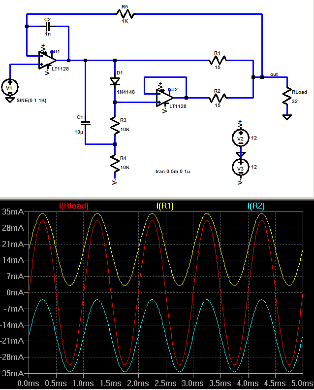
from:
AD8397-class A? - Page 2 - Head-Fi: Covering Headphones, Earphones and Portable Audio
I know these techniques can reduce measurable distortion to -160 dB (indirect IMD test, extra gain and long averaging) with my op amp circuits driving 32 Ohm loads, similar results shoud be available to power chip amp builders
I don't know if these techniques are "necessary" - but the effects they address are real and the solutions I propose do reduce these distortions in the output rather than just "rearrange" them
thermal time constants in the Si chip are much faster than the package-heatsink and can be in the low audio range
looking at SMTE or other low+high frequency IMD with heavy loads usually reveals likely thermal caused errors
some additional power related errors can come from the shared supply pins with the output devices heavy currents giving ps common impedance coupling to the earlier amplification circuitry
using a lower noise input op amp in a separately supplied, physically separated package, closing a outer feedback loop around the power chip amp avoids multiple error mechanisms
the classic "bad high feedback" amplifier perception may date from 70's amps boasting low % THD - with full scale output, but under-biased outputs may have given large % distortion at lower, common listening levels
Today designers with as diverse opinions as Bob Cordell, John Curl and Nelson Pass (Pass goes Class A mostly now days) here are proposing very high output device bias in discrete amps - 100s of mA - why wouldn't we try that with chip amps as well? Dr Geddes - of the GedLee distortion metric advocates testing amps for nonlinearity at very low levels
Class A output stage bias does avoid several distortion mechanisms, in exchange for efficiency - even Douglas Self agrees - the question is only whether the trade off is "worth it"
I have biased "chip amps" (LM6172, TPA6120, LT1210) into full Class A for headphone amp use
this sim shows the push-pull bais principle:
from:
AD8397-class A? - Page 2 - Head-Fi: Covering Headphones, Earphones and Portable Audio
I know these techniques can reduce measurable distortion to -160 dB (indirect IMD test, extra gain and long averaging) with my op amp circuits driving 32 Ohm loads, similar results shoud be available to power chip amp builders
I don't know if these techniques are "necessary" - but the effects they address are real and the solutions I propose do reduce these distortions in the output rather than just "rearrange" them
Last edited:
Quote:
Originally Posted by a.wayne View Post
i currently pop 10 amps fuses ( speaker side) from time to time,
Quote:
Originally posted at http://www.tradebingo.com/1pekingroa...e&orderby=desc post #147
The Maggies have been designed to feature a purely resistive and ruler straight impedance curve so theoretically speaking at least, the impedance does not drop, like many other dynamic speakers do, on either end of the frequency spectrum. The thing that goes wrong is the speaker frame. It is not strong enough to withstand the shrinkage inflicted by the grille cloth (our diehard planar freak, thekong, had his T4 stripped naked and he has never had the same problem). As a result, the frame becomes bent from both sides, thereby lifting the magnets away from the Mylar film where the “voice coil” lies. Magnetic field reduces dramatically over distance and hence what we may have is a near short-circuit when situation gets real worse.
Since the Mylar (the mid and bass panel) is reluctant to take 98% of the load, the ribbon, being a separate entity hooked via the crossover, has to suffer to take all the power imposed. When bass becomes inevitably lean as a result of the warping, people tend to turn the volume up further, making the situation even worse. This explains why old Maggies tend to burn their ribbons or fuses frequently.
.
Not for me , i don't have maggies , I had listened to a Pr of maggies! I'm running a direct drive 3 way ribbon 1.2 z min and do pop 10 amp speaker fuses when listening spirited ...
actually there can be several thermal effects - the symetric/quad diff pair layout does greatly reduce Vos modulation effect, but Hfe of all of the transistors are temperature sensitive, VAS and Output will have gain modulation – look for Bob Pease “output modulation” article
thermal time constants in the Si chip are much faster than the package-heatsink and can be in the low audio range
looking at SMTE or other low+high frequency IMD with heavy loads usually reveals likely thermal caused errors
some additional power related errors can come from the shared supply pins with the output devices heavy currents giving ps common impedance coupling to the earlier amplification circuitry
using a lower noise input op amp in a separately supplied, physically separated package, closing a outer feedback loop around the power chip amp avoids multiple error mechanisms
the classic "bad high feedback" amplifier perception may date from 70's amps boasting low % THD - with full scale output, but under-biased outputs may have given large % distortion at lower, common listening levels
Today designers with as diverse opinions as Bob Cordell, John Curl and Nelson Pass (Pass goes Class A mostly now days) here are proposing very high output device bias in discrete amps - 100s of mA - why wouldn't we try that with chip amps as well? Dr Geddes - of the GedLee distortion metric advocates testing amps for nonlinearity at very low levels
Class A output stage bias does avoid several distortion mechanisms, in exchange for efficiency - even Douglas Self agrees - the question is only whether the trade off is "worth it"
I have biased "chip amps" (LM6172, TPA6120, LT1210) into full Class A for headphone amp use
this sim shows the push-pull bais principle:
from:
AD8397-class A? - Page 2 - Head-Fi: Covering Headphones, Earphones and Portable Audio
I know these techniques can reduce measurable distortion to -160 dB (indirect IMD test, extra gain and long averaging) with my op amp circuits driving 32 Ohm loads, similar results shoud be available to power chip amp builders
I don't know if these techniques are "necessary" - but the effects they address are real and the solutions I propose do reduce these distortions in the output rather than just "rearrange" them
SO has anyone tried a class-a lm3886's or lm4780's chip amp
- Status
- This old topic is closed. If you want to reopen this topic, contact a moderator using the "Report Post" button.
- Home
- Amplifiers
- Chip Amps
- So just how "good" can a chip amp be ?