So - decided to build myself an insane headphone amp.
Im going to build it using the guidelines on this site for low distortion, low noise construction, no C-in, film caps etc.
So far, my choice of chip is an LM1875 power amp. I know its massively overkill for an headphone amp, but i do plan on winding down the gain, and putting in a attenuator using non wire wound resistors to reduce noise.
So, is LM1875 a good chip for headphone amps?
Last edited:
Portable 9V Headphone Amplifier by NE5532 | Circuit Project Electronic is something i just found.
holy crap, i dont think im going to go this far, i only have a 60 dollar set of Phillips SBC-HP250 headphones!
found something that look like this one..
http://www.diyaudio.com/forums/soli...urrent-discrete-audio-buffer.html#post2055398
http://www.diyaudio.com/forums/soli...urrent-discrete-audio-buffer.html#post2055398
To adjust the bias, a pot in serial with one of the diodes will
be enough., although it s useless as the strip of 6 diodes makes the
amp biased in class A.
The current is limited by the power devices emitter resistors.
You can also change these resistors to choose your bias.
It is very stable anyway.
also, you can use two darlingtons as power devices, this will make the
circuit even more simple, and that s what i made mysef.
The same, apart with darlingtons at the output.
The op amp used will define the distorsion rate.
So far, with the old 5532, it s about 0.002%
for a 2.5V output at 10khz and 0.0004 % at 1khz.
The serial output 18R must be settled according to
your phone impedance, so it will surely be between 18 and 50R.
Bias is about 100mA in the two versions, and can be increased
or reduced proportionaly to the 3.3R emitter resistors tweaking.
Attachments
so its more of a class A amp.
I like it!
Thats why you warn to mount the transistors on heatsinks, power dissipation.
Right, rainwulf, they disspate about 1W each.
Mouned on the casing should be enough to cool them.
Also, the DC supply is kept low to reduce thermal dissipation.
Of course , you can increase it to +-15V , but i doubt a phone will
need that much power.
Thank you wahab, that looks like the perfect circuit for me to throw together.
Do you have params on those darlingtons? Just in case i cant get them.
Are they specific?
They have nothing special apart from being dirt cheap.
You can also use BDW93C/94C which are more rugged,
but as cheap as the ones on the schematic.
Here their caracteristics.
Attachments

I've built a very satisfying class A headphone amp with little more than a good opamp and a couple MOSFETs. Set one up as a constant current sink. Though everybody thinks symmetry is good (hey, it might be if you could actually achieve it), the voltage offset involved in driving a MOSFET moves the opamp signals away from the crossover area, making it that much better. I'll try to dig up a schematic for the thing.
Conrad
Conrad
Here's a super simple circuit. You can bias it low for headphone use or, with a large heat sink, bias it high enough for small speakers. Just be sure the heat sink is adequate. Today I'd use an LME opamp, but 5532 or 5534 is very good. MOSFET choice is non-critical and it's also nice because no P channel devices are needed. I'd also use a polypropylene cap rather than a mylar.
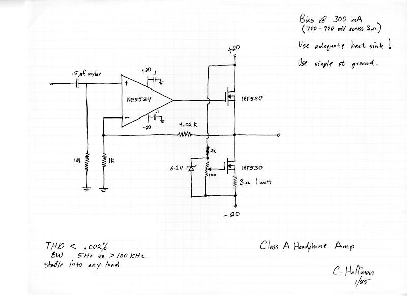
Headphone Amp from 1985!
I also did a version with an active current sink, but it really didn't offer any great benefit other than using more parts.
Conrad
Headphone Amp from 1985!
I also did a version with an active current sink, but it really didn't offer any great benefit other than using more parts.
Conrad
LME49600 specified distorsion is with a unity gain.
With a 20db gain its distorsion will increase ten folds.
so it must be used as unity gain buffer, needing an op amp to
drive it...
Oddly, the circuit is not usable with a unity gain, unless a
1nF caps is used to reduce the lack of damping, and this
will reduce the unity gain bandwith to less than 10mhz, the same
as many low cost op amps..
Its current output is limited to 250mA peak.
The other project i see by there use IRF mosfets.
I personnaly tested these devices, and they have
a serious drawback as they will limit the max output voltage
due to a 4.5v threshold, not counting that they produce
significantly higher distorsion than BJTs despite a higher
bias current.
Last edited:
- Status
- This old topic is closed. If you want to reopen this topic, contact a moderator using the "Report Post" button.
- Home
- Amplifiers
- Chip Amps
- Designing a super low distortion headphone amp.