I need your help")
My 100k linear pot is not going very well, and I'm thinking about another solution for my gainclone as Loesch.
Should a 50K linear pot better? Could a 22K from inverting output to ground fix everything?
If I use the shunt attenuator suggested in Nuuk site, Should I keep the 10K resistor? That is, any atenuattor I'd use, should be it instead of only the pot?
Hey, my gainclone is just equal to my denon1801, and I need help to take off
Thanks, prokofieff is waiting also for your help.
If I use the shunt attenuator suggested in Nuuk site, Should I keep the 10K resistor?
Hi Raka, if you mean the 10K input resistor, then yes, that is an essential part of the circuit.
The stepped attenuator mentioned on my site is used instead of a pot. And after a week of listening to mine I can tell you that it works very well. I have yet to hear a pot than can compete with a stepped attenuator, the case against attenuators usually being the cost.
In the case of the 12 step version, the switch will cost you about 15 euros and the resistors, well it depends on where you get them from and what you use. I suggest starting off with a good quality item for the series resistor, ie Welwyn RC55 and just using 1% metal films for the shunt resistors.
Thanks Nuuk,
I change the pot to a 50K one, and I think works better. Is there more gain? It seemed so.
If I keep the 10K resistor, I will have two series resistor in this order: phonostage-10k-rotaryswitch-10uF-10K-Inverting input. Is this ok?
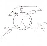
I bought yesterday the rotary switch, but I'm not sure which is the best way to connect the resistors.
If I do like in the picture below I will need to make kind of an outer ring for the signal ground, won't I? Is there any other cleaner way to do this?
Sorry for the "autocad" format
BTW, Have I told you latelly that I like your site? How is your tt doing?
I change the pot to a 50K one, and I think works better. Is there more gain? It seemed so.
If I keep the 10K resistor, I will have two series resistor in this order: phonostage-10k-rotaryswitch-10uF-10K-Inverting input. Is this ok?
I bought yesterday the rotary switch, but I'm not sure which is the best way to connect the resistors.
If I do like in the picture below I will need to make kind of an outer ring for the signal ground, won't I? Is there any other cleaner way to do this?
Sorry for the "autocad" format
BTW, Have I told you latelly that I like your site?
How is your tt doing?Attachments
If I keep the 10K resistor, I will have two series resistor in this order: phonostage-10k-rotaryswitch-10uF-10K-Inverting input. Is this ok?
Raka, forget the phono stage, keep that as a separate issue to lessen the confusion. So yes, you have the series resistor for the attenuator (which is just a variable voltage divider!), then your input (DC blocking) capacitor, and then the input resistor for the amp.
Your drawing of the attenuator wiring if fine, and yes, a ring will make for neater construction - you could make one by winding some stiff copper wire around someting round to use as a former.
Or you could make up a dummy wafer but all this information is on the GC beginner's page of my web site!!!
As I said in my previous post, I am using the 12 position stepped attenuator built on the rotary switch/wafer mechanism and using the resistor values as recommneded by Thorsten for the IGC.
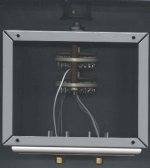
I built my 12-step attenuator a different way, I kept the input impedance for the source device constant.
GainClone page: http://gainclone.platenspeler.com (page 2, building process)
And some background on attenuator and how to calculate the resistor values (Excel spreadsheet) on:
http://www.platenspeler.com/background/attenuator/uk_attenuator_1.html
Works fine for me...
Maarten
GainClone page: http://gainclone.platenspeler.com (page 2, building process)
An externally hosted image should be here but it was not working when we last tested it.
And some background on attenuator and how to calculate the resistor values (Excel spreadsheet) on:
http://www.platenspeler.com/background/attenuator/uk_attenuator_1.html
Works fine for me...
Maarten
Hi,
I built this one with all the same resistors and connected a resistor across the output. This doesn't make perfect logarithmic pot near the very low and very high volumes. However, in the middle, I get really nice 1dB per step characteristics.
114 K ohm 5 K ohm per step (supposedly 115K but measures 114K) Bypassed at the output with 10K. You can see the same results in an article at Elliot Sound.
I think it sound pretty good.
Tomo
Attachments
platenspeler said:I built my 12-step attenuator a different way, I kept the input impedance for the source device constant.
Thanks for the picture, it's the same rotating switch I have
Yes, I think that yours is a more simple way to build it. One question, the cable in your picture seems to be a shielded one, wasn't only necessary to bring there the "live" wire?
Have you found advantage for the constant impedance?
Now, the 12 fantasies for solo violin from Teleman are playing in continous mode,
in a 12bar shuffle:
Burn in,
When are you coooming,
Burn in,
I'm a fooool for your loving
Sorry for the voice, it's very early...
The shielded cable brings ground and input to the switch, the teflon isolated wire goes to the input of the Power Opamp. The output on the wiper and input and ground form a voltage devider for the input of the PowerOpamp. (see second link in my previous post for a picture of the connections)Raka said:platenspeler said:I built my 12-step attenuator a different way, I kept the input impedance for the source device constant.
Thanks for the picture, it's the same rotating switch I have
Yes, I think that yours is a more simple way to build it. One question, the cable in your picture seems to be a shielded one, wasn't only necessary to bring there the "live" wire?
Have you found advantage for the constant impedance?
B.t.w, most of these 12-step Lorlin switches are sold in the Break-before-Make version. This means that between two positioons of the switch there is no connection on the output for a short while. This means that during this short period the GainClone has no input impedance and will make nasty noise. This can be avioded by soldering a 47-k resistor in parallel over wiper and ground.
Of course it is simpler to get a Make-Before-Break type of this switch but I found only a few of these and most distributors do not stock these switches.
gr,
Maarten
- Status
- This old topic is closed. If you want to reopen this topic, contact a moderator using the "Report Post" button.
- Home
- Amplifiers
- Chip Amps
- Attenuator