i've recently bought the LM1876 IC chip and the datasheet does not offer any help as to what kind of circuit should be used if the person wishes to use the standby and/or mute functions. it also does not show wether to connect it to the positve voltage Vcc ot the negative voltage Vee.
Can anyone help me with a simple schematic and explanation of what to use if i wish to use both mute and standby.
Thanks.
Can anyone help me with a simple schematic and explanation of what to use if i wish to use both mute and standby.
Thanks.
From Reading the Datasheet it seems that the Mute and Standby functions are controlled by a Logic gate , logic-high voltage will mute it and Logic-low voltage will un-mute it , it is simular for the Standby function .....
Since I don"t have a clue about logic gates I couldn"t tell you how to implement it ......
In appliciation information it talks about the Mute and standby pins but I can"t make heads or tails of it ......
http://www.national.com/ds/LM/LM1876.pdf
Since I don"t have a clue about logic gates I couldn"t tell you how to implement it ......
In appliciation information it talks about the Mute and standby pins but I can"t make heads or tails of it ......
http://www.national.com/ds/LM/LM1876.pdf
how to implement LM1876 mute?
I'm struggling to find a simple way to use the mute function on LM1876. I can't program microcontrollers yet. Also I would not like to use relays if possible.
The easiest thing would be to have a separate switch, but this is not very convinient.
I thought of below switch arrangement.
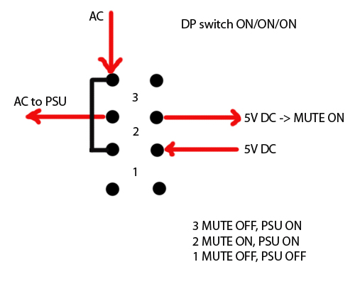
Would this work?
When switching off, one would need to wait in POS 2 for a few sec")
The 5V would come from a battery.
Does anyone know some elegant and easy ways to handle mute pins of these kind of chipamps?
I have built a LM3886 gainclone - runs nicely, but pops like crazy (did not use mute pins).
I'm struggling to find a simple way to use the mute function on LM1876. I can't program microcontrollers yet. Also I would not like to use relays if possible.
The easiest thing would be to have a separate switch, but this is not very convinient.
I thought of below switch arrangement.
Would this work?
When switching off, one would need to wait in POS 2 for a few sec
The 5V would come from a battery.
Does anyone know some elegant and easy ways to handle mute pins of these kind of chipamps?
I have built a LM3886 gainclone - runs nicely, but pops like crazy (did not use mute pins).
It may help if you would describe in what circumstance you are going to use this amplifier . The mute function works just like an lm 3886. I have built quite a few lm3886 amplifiers have never used the mute function and apart from the slightest click not even as loud as the power switch itself i have had no problems. with popping noises like crazy
It will be used as a common stereo amplifier, schematic is almost as the one in the datasheet.
I have added bleeder resistors and snubber to PSU, the LM3886 amplifier doesn't have those. As a side note - the LM3886 amplifier also has a low gain 2 stage preamp with opamps. When changing preamp opamps, the pop characteristics change as well.
I have added bleeder resistors and snubber to PSU, the LM3886 amplifier doesn't have those. As a side note - the LM3886 amplifier also has a low gain 2 stage preamp with opamps. When changing preamp opamps, the pop characteristics change as well.
The circuit in post #5 would work.
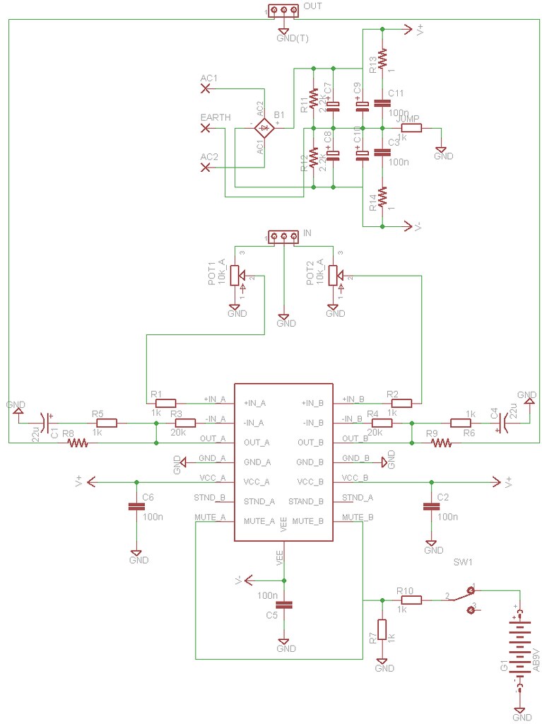
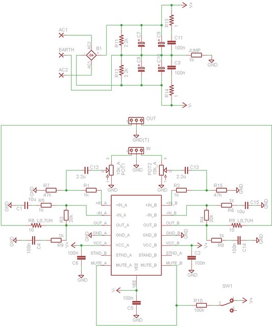
You could simplify the mute section in post #7. Remove R7 and replace R10 with 100k. Skip G1 and connect SW1 pin 1 to V+.
To eliminate popping, use capacitors (Cin) between pot and R1/R2. Add a resistor to ground between the cap and R1/R2 (Rin).
The muting on the LM1876 does not work the same as the the LM3886. The LM3886 is current controlled. No current means mute, more than 0,5 mA means sound. The LM1876 is voltage controlled. No voltage means sound, more than 2,5 V means mute.
The mute and standby functions are switch-enabled, so convenience only applies to how the switch is implemented. That is a personal preference. If desired, perhaps a simple timer could be added to the power-on switch that would disable the function after a brief pause. That seems to me to be what the goal is here, rather than a "mute 'cause the phone is ringing" feature. The datasheet doesn't go into much detail other than to say a logic-level signal is required; there's umpteen ways to get there from here, so they leave it to the designer.
AndrewT - R3 and R4 are feedback resistors to provide AC gain together with R5 and R6. Well, I did scratch my head for a moment, the layout is messy due to this self made Eagle package
Thanks pacificblue, I'll implement the changes.
I was almost about to lay that chip aside, since there are similar chips around that have built in pop suppression (LM4766).
Thanks pacificblue, I'll implement the changes.
I was almost about to lay that chip aside, since there are similar chips around that have built in pop suppression (LM4766).
It makes sense to keep the mute on for a moment after power on, powering off seems a bit more tricky. The amp pops after power is disconnected, this is why I had first a battery in mind that would operate the mute in that situation. Perhaps some primitive energy storage/timer could be constructed with a cap and some discrete parts.
I need to think about this, all suggestions are welcome!
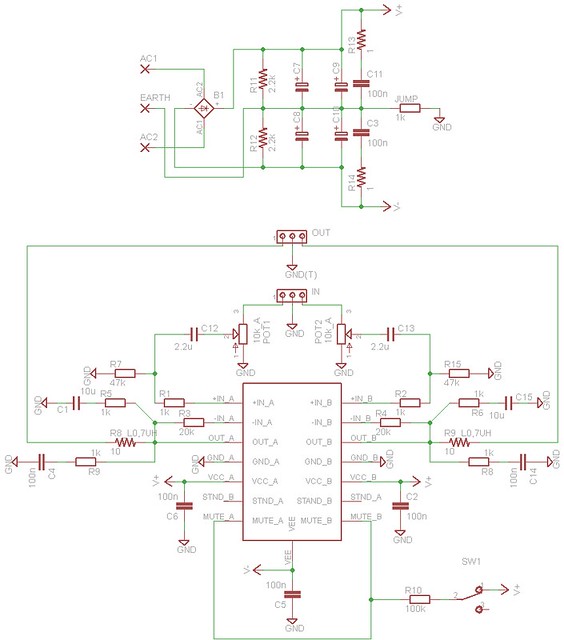
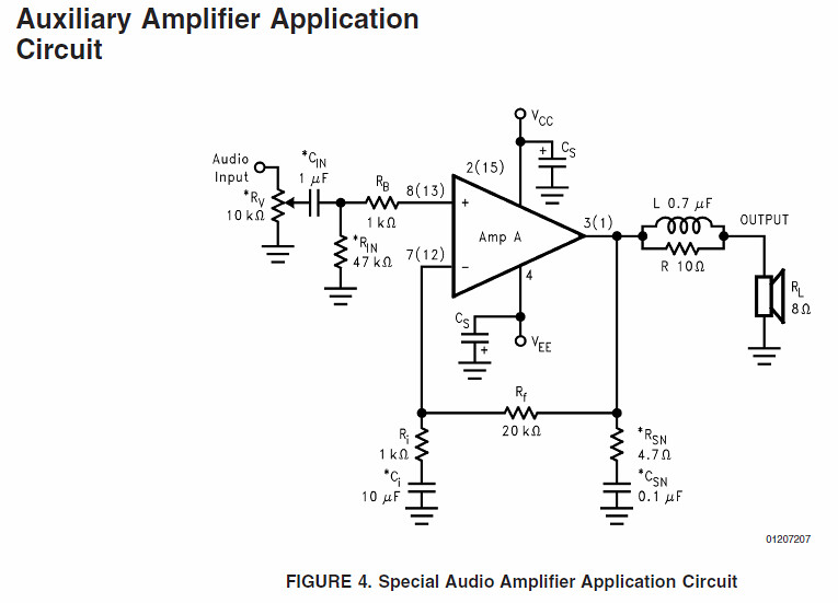
Implemented the suggestions from pacificblue. I noticed the first version I did was according to the basic datasheet schematic, but there was also a more "complete" one given. So I added R8, R9 and C4, C14 - supposed to prevent high freq. oscillation.
I need to think about this, all suggestions are welcome!
Implemented the suggestions from pacificblue. I noticed the first version I did was according to the basic datasheet schematic, but there was also a more "complete" one given. So I added R8, R9 and C4, C14 - supposed to prevent high freq. oscillation.
hello.
r5,r6 connected wrong?
Thanks for pointing to it. R5, R6 are really wrong.
This should be correct.
Last edited:
You sorted R3 & R4.
Now they are in the NFB loop.
Yup, now the thing might even work. I missed those at first.
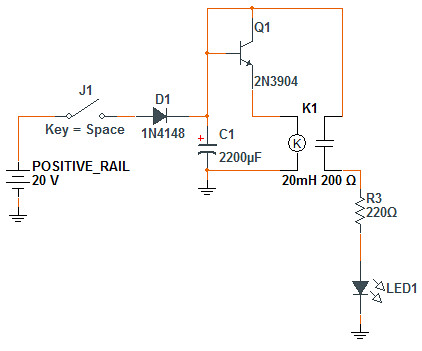
I searched for usable solutions on the internet and simulated an OFF delay like this.
It keeps the LED (mute pin) lit for about 3sec after poweroff.
What could I improve in the circuit?
I have some existing amplifiers that pop loudly, mostly when powering off.
One of those is a LM3886 gainclone and another one are the M-AUDIO AV40 nearfield monitors. It is especially dissapointing that the monitors pop.
I suspect that the mains wiring in my house may have the earth connection missing in a number of sockets.Will have to try to run the devices in a different room.
Could the missing earth cause poping as well?
- Status
- This old topic is closed. If you want to reopen this topic, contact a moderator using the "Report Post" button.
- Home
- Amplifiers
- Chip Amps
- need LM1876 mute mode and standby mode help