I'm basing this design heavily on Rod Elliots P88. I would just use his design, but I don't care for his board design with the switches in the middle of the board for gain selection. Nifty, but it doesn't look like a finished project. Since I'm not using his board, I figured I'd change the design a little too.
Signal path:
Buffer > Vol control > 6db gain stage
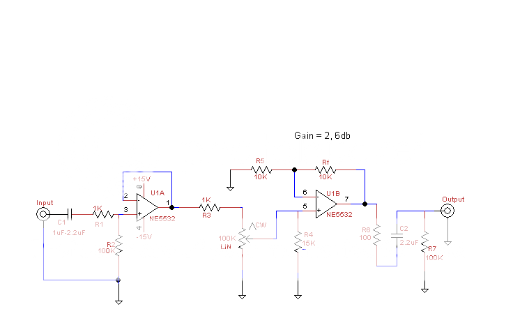
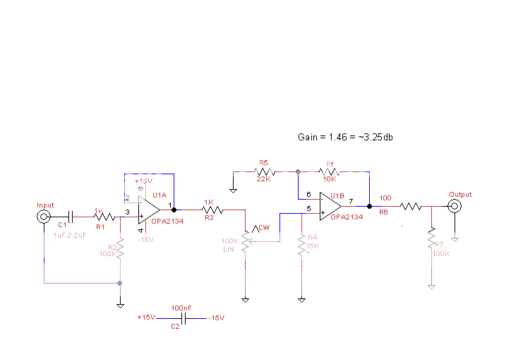
The buffer is there to drive the volume control, and then a small gain stage. I am wondering if the order should be reversed, gain stage > vol control > buffer. And, I might go with a less gain, 3db instead of 6db, but thats a minor detail. I may eventualy use a better opamp, LM4562 or similar.
Is there a simple way to make sure there is zero output dc offset, to get rid of the output cap? Can an Rc be used? I've already started working on the board layout and will be posting progress soon.
A balanced xlr output stage will be added after this, but I'm pretty much going to use Rod's design for that. Power supply will just be LM317/337 +/-15Vdc.
Comments?
Signal path:
Buffer > Vol control > 6db gain stage
The buffer is there to drive the volume control, and then a small gain stage. I am wondering if the order should be reversed, gain stage > vol control > buffer. And, I might go with a less gain, 3db instead of 6db, but thats a minor detail. I may eventualy use a better opamp, LM4562 or similar.
Is there a simple way to make sure there is zero output dc offset, to get rid of the output cap? Can an Rc be used? I've already started working on the board layout and will be posting progress soon.
A balanced xlr output stage will be added after this, but I'm pretty much going to use Rod's design for that. Power supply will just be LM317/337 +/-15Vdc.
Comments?
Last edited:
Using a FET opamp will eliminate offset... using a bipolar as you show will cause significant offset due to unmatched impedances on the - and + inputs.
It's never a good idea to amplify, and then throw that gain away, and amplify again as the noise (all be it small for line level) adds up.
What's an RC") Remote control ? Or a resistor/cap network somewhere ?
Remote control ? Or a resistor/cap network somewhere ?
It's never a good idea to amplify, and then throw that gain away, and amplify again as the noise (all be it small for line level) adds up.
What's an RC
Remote control ? Or a resistor/cap network somewhere ?Suggestions on which opamp to use?
Sorry, Rc is an input offset compensation resistor. It equalizes the +/- input impedances. With non-inverted stages it is calculated by Rc = (Rf//R1)-rs and it is put in series with the + input. I was going to include it, but with the varying source resistance from the volume control pot I didn't know how it should be calculated.
Sorry, Rc is an input offset compensation resistor. It equalizes the +/- input impedances. With non-inverted stages it is calculated by Rc = (Rf//R1)-rs and it is put in series with the + input. I was going to include it, but with the varying source resistance from the volume control pot I didn't know how it should be calculated.
Suggestions on which opamp to use?
Sorry, Rc is an input offset compensation resistor. It equalizes the +/- input impedances. With non-inverted stages it is calculated by Rc = (Rf//R1)-rs and it is put in series with the + input. I was going to include it, but with the varying source resistance from the volume control pot I didn't know how it should be calculated.
As you say, the varying impedance means you can't optimise the design for zero offset.
Opamps... Well I keep coming back to the OPA2604 however there are many good devices out there. Why not initially fit a socket and try different ones ?
But it must be FET input to avoid DC offset issues.
Also decouple the opamp across it's supply pins, preferably on the device itself with a small (0.1uf) cap, and perhaps also a low ESR electroylitic in parallel nearby on the PCB.
Don't decouple rail to ground as a general guide as that introduces PSU noise into the signal ground unless you opt for separate signal and PSU grounds which on a preamp isn't needed really.
Don't decouple rail to ground as a general guide as that introduces PSU noise into the signal ground unless you opt for separate signal and PSU grounds which on a preamp isn't needed really.
What about the balanced output driver stage? Rod's design shows no output coupling. Is dc offset canceled out in the receiver end?
Project 88
Fig 2 is a FET opamp so no problem DC wise.
Fig 4 also FET opamp so again no DC problem. The caps are there because as a designer you have no way of knowing what someone may try and connect to it. It's just a safegaurd and good commercial practice...
http://sound.westhost.com/project88.htm
Also decouple the opamp across it's supply pins, preferably on the device itself with a small (0.1uf) cap, and perhaps also a low ESR electroylitic in parallel nearby on the PCB.
Don't decouple rail to ground as a general guide as that introduces PSU noise into the signal ground unless you opt for separate signal and PSU grounds which on a preamp isn't needed really.
Thats good to know. Rod decouples the power pins to ground. Going from + to - pins will save some space on the board. I hadn't put them on the schematic, but I planned on doing it the "normal" way. I'll probably go your way. And, I may just the OPA2134 and drop the output cap.
What about the balanced output driver stage? Rod's design shows no output coupling. Is dc offset canceled out in the receiver end?
Gotta go, but what do you mean "balanced output driver stage " it's all single ended, not balanced... where are you looking ?
Any particular reason for driving the volume pot with an opamp? I just recently made a simple opamp-based preamp myself with a 100k log volume pot followed by a 100k balance pot followed by a single gain stage and it seems to work just fine. The dc-offset does vary with the volume and balance settings, but I dealt with that and other DC-offset sources using a DC-servo loop. Opamps I used were LME49720 for the gain and LF412 for the servo.
Last edited:
Any particular reason for driving the volume pot with an opamp? I just recently made a simple opamp-based preamp myself with a 100k log-volume pot followed by a 100k balance pot followed by a single gain stage and it seems to work just fine. The dc-offset does vary with the volume and balance settings, but I dealt with that and other DC-offset sources using a DC-servo loop. Opamps I used were LME49720 for the gain and LF412 for the servo.
So, even an opamp with FET inputs will have varying dc offset with the variable source resistance of a vol control?
Sorry to post Rod's image, but this is the balanced line driver I'm going to use. It's from P51.
An externally hosted image should be here but it was not working when we last tested it.
I don't know whether LME49720 has FET inputs, but the datasheet shows 10nA input bias (so certainly not MOSFET anyway) and 0.1mV Vos. Considering that my amp has voltage gain of 50, it does indeed produce tens of millivolts of DC offset on the output, something that I learned only after building the first version of my little amp. (Another thing I learned the hard way with that circuit was that resistors produce significant noise. I had never even though about that before.)So, even an opamp with FET inputs will have varying dc offset with the variable source resistance of a vol control?
Maybe the DC offset is not so much a problem for you if you only have a gain factor of two.
Also, regarding the order of the stages: I'd put the gain stage first, if possible. That way you avoid amplifying noise from the previous stages. (I learned that the hard way too.)
Last edited:
Just did some testing with the 2nd circuit shown with an NE5532P from Texas Instruments. Output offset varied from +3mVdc to -27mVdc with turning the vol control pot from min to max. Most of the offset is coming from the buffer; there's -20mvdc on pin 1.
I then dropped in a TL072 and output offset dropped to .1mVdc - .8mVdc. depending on where the vol control was. Big difference with the fet opamps for a direct coupled circuit.
I then dropped in a TL072 and output offset dropped to .1mVdc - .8mVdc. depending on where the vol control was. Big difference with the fet opamps for a direct coupled circuit.
Just did some testing with the 2nd circuit shown with an NE5532P from Texas Instruments. Output offset varied from +3mVdc to -27mVdc with turning the vol control pot from min to max. Most of the offset is coming from the buffer; there's -20mvdc on pin 1.
I then dropped in a TL072 and output offset dropped to .1mVdc - .8mVdc. depending on where the vol control was. Big difference with the fet opamps for a direct coupled circuit.
You're probably seeing the bias current of the 5532 on the 100K resistor. You might find it interesting to reduce the value of the 100K to 10-15K and see if the offset tracks toward 0. I expect it will. Unless you're interfacing with tube gear, it's probably better to stay below 22K. I usually shoot for 10K.
G²
New schematic with changes...
An externally hosted image should be here but it was not working when we last tested it.
you can use a 1k resistor from output to inverting input
of the buffer stage, rather than a short circuit, this will
greatly reduce the output dc offset of this stage by
balancing the two inputs dc impedances...
You're probably seeing the bias current of the 5532 on the 100K resistor. You might find it interesting to reduce the value of the 100K to 10-15K and see if the offset tracks toward 0. I expect it will. Unless you're interfacing with tube gear, it's probably better to stay below 22K. I usually shoot for 10K.
Tried dropping it to 10K, no change in offset voltage.
you can use a 1k resistor from output to inverting input of the buffer stage, rather than a short circuit, this will
greatly reduce the output dc offset of this stage by
balancing the two inputs dc impedances...
Tried this, and even though it makes perfect sense, no change.
If I drop R2, the 100K, down to 22K the dc offset on pin 1 drops to ~5mVdc but that will make my input impedance way too low.
Last edited:
R4 should be equal to the impedance "seen" by the inverting input of the op-amp. I.e. R4 = R5||Rf. For your values of 10k, 22k, R4 works out to 6.88 kOhm. 6.8k is probably close enough. Similarly, you could insert a 1k from pin 1 to pin 2 of U1A and compensate for its input bias current. This won't change the gain.
I don't see a purpose for R3. Unless you like adding thermal noise, I suggest taking it out.
I would put the amplifying stage before the volume control to avoid attenuating before amplifying. It'll be better for the noise performance, though, in your case with a 3 dB gain, you probably won't notice the difference.
I suggest bandwidth limiting the first stage. I'd set a pole there at about 200 kHz. So C =1/(2*pi*1000*200E3) = 795 pF. I'd probably use 820 pF as this is a standard value. Or 680 pF... It'll limit clicks and pops that you otherwise would get every time an appliance or other heavy energy-sucker turns on. It'll also limit EMI from your cell phone and WiFi devices.
Good circuit, though. I suggest using an LME49720. Those amps are superb. My preamp is a design similar to yours (with the changes I suggest above) except I use a PGA2310 volume control IC.
~Tom
- Status
- This old topic is closed. If you want to reopen this topic, contact a moderator using the "Report Post" button.
- Home
- Amplifiers
- Chip Amps
- Basic opamp based preamp