great work from rod, but isn t it somewhat
too risky fr someone that begin building electronic items ?.
you did manage to find this circuit easily?...
in another thread, a guy that was looking for the same
kind f amp did write that it was obsolete...
anyway, it should work flawlessly if you respect the
schematic, which is simple...
good luck in your try !!
Philips IC 17-pin ZIP Dual Audio Amplifier | Distributed By MCM
ST IC 5-pin Zip-hs Tda2040v Single Audio Amplifier | Distributed By MCM
Thanks everybody!
LA4628? Very easy and quite enjoyable.
yes, it s an equivalent circuit in perfs, although it needs
much more external components, and is less rugged than the phillips,
32.5W TDP vs 60 W TDP....
yes, it s an equivalent circuit in perfs, although it needs
much more external components, and is less rugged than the phillips,
32.5W TDP vs 60 W TDP....
That's odd. The chip with the larger thermal interface has about half the TDP? Really?
One LA4628 on 17.5vdc can run ONE 4 ohm speaker for long term use without breaking down (test used only one channel--not parallel mode). On this test, I was checking durability (voltage per load), not thermal.
It has run this subwoofer Parts-Express.com:*Dayton RS180-4 7" Reference Woofer 4 Ohm | rs225-4 7" woofer midbass rs aluminum cone phase plug dayton long term and continues to operate as expected (a miniature earthquake).
I'm not sure how this test relates to running two speakers on 12vdc regulated power, but it seems that the durability is sufficient.
Since the lowest of notes in music are much louder than expected, I, personally, had no means to compare efficiency of this amplifier. My test was purposefully inefficient to check durability. All I can tell you is that its very clear, and very entertaining.
")
Last edited:
yes, distorsion is somewhat high, that s why i first proposed to use a TDA2040....
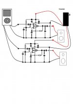
i did build a TDA1558Q amp a few days ago, and i did choose
the bridge configuration as at low power, it allows a distorsionless
sound even at 2 X 10 W...
anyway, the four amps needed to build a stereo bridged amp
are all in the same casing, and the circuit is very simple to implement...
You got me curious, so I bought a pair of TDA1558Q.
lol...hope it will be a good sounding to yours ears...
i didn t find the circuit in the current phillips/nxp
catalog...
it has been replaced since 1997 by the TDA8561Q
wich very marginal improvements and an formerly unused
pin is now used to give informations about output stages
saturations/temperature..the rest stay exactly the same..
anyway,i was first suspicious about this IC, but i mst
aknowledge that it s hard find better , moreover if
we look at the ease of implementation.
Can somebody explain the grounding system to me? I've read some stuff but it gets a little confusing... they mention secondary and primary groundings (never explaining what's secondary and primary).
Both types of chips I bought have metal backsides. So I assume that means they are non-insulated, so I will need some sort of insulator between them and the heatsink?
Both types of chips I bought have metal backsides. So I assume that means they are non-insulated, so I will need some sort of insulator between them and the heatsink?
I don"t know what they mean by primary grounds ,
The secondary ground would be the center tap on a center tapped secondary transformer or on a single secondary transformer it would be the Wire that you use to create your DC ground .....
The primary ground could refer to to Common in Your Houses Ac line or it could be the safety ground from your walls AC outlet ......
You will need to get a Transistor mounting kit with your heatsink , it is simply a Insulation pad for the Chip and a Plastic ring that isolates the mounting bolt from the Chip , and heatsink compound is also needed ....
After mounting the chip use a Multi meter to check if the chip is isolated from the heatsink , Ive had a few occations after mounting and thinking it was isolated only to find it wasnt after checking ......
cheers
I guess that transformer stuff makes sense since I was looking at a site that addressed typical gainclones... not this atypical approach.
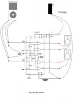
So all grounds will go to the same place? Because the schematic for the 1558Q differentiates between two of the grounds: one goes to signal ground, one goes to power ground (substrate), and another is shown going to a non-specified ground.
And the TDA2040 just shows things going to ground without explanation.
I also read something somewhere which said any grounds coming on the amplification side need to be grounded closer than the signal grounds, so the signal doesn't get corrupted.
I guess that transformer stuff makes sense since I was looking at a site that addressed typical gainclones... not this atypical approach.
So all grounds will go to the same place? Because the schematic for the 1558Q differentiates between two of the grounds: one goes to signal ground, one goes to power ground (substrate), and another is shown going to a non-specified ground.
And the TDA2040 just shows things going to ground without explanation.
I also read something somewhere which said any grounds coming on the amplification side need to be grounded closer than the signal grounds, so the signal doesn't get corrupted.
TDA1558 signal ground is simply connected to the others grounds,
only be cautious that the input cable shiled must be connected near the
signal ground pin, not near the point where all grounds are connected
together...
TDA2040 has the NEGATIVE supply to the case, so in the single supply
variant, it will be the ground...
anyway, keep the cases isolated if the heatspreaders are to be
in contact with a metallic casing....
TDA1558 signal ground is simply connected to the others grounds,
only be cautious that the input cable shiled must be connected near the
signal ground pin, not near the point where all grounds are connected
together...
TDA2040 has the NEGATIVE supply to the case, so in the single supply
variant, it will be the ground...
Sorry I refer to things in household electric terms.
So to clarify:
On TDA1558, the shields from the input terminate at pin 3 on the chip. And the rest of the grounds all come together at the star ground, which then ties into the negative coming from the transformer.
On TDA2040, all grounds come to the star ground which then ties into the negative coming from the transformer.
And does the case get grounded also (assuming I use metal)? Thanks
Sorry I refer to things in household electric terms.
And does the case get grounded also (assuming I use metal)? Thanks
in tda1558Q, the case is connected to the ground, anyway, so there s
no use to connect it to the star point, moreover, it s better to isolate it..
as already said, the case of the tda2004 isINTERNALLY connected to the
negative supply, not the ground..it happens that if the ic is used
with a single supply, the case will be ground connected, so
it s useless to connect this case to ground...
as i said, keep them isolated to prevent ground loops..
hope it helps..
Hi,And does the case get grounded also (assuming I use metal)? Thanks
no.
The case/chassis MUST be permanently connected to Safety Earth.
in tda1558Q, the case is connected to the ground, anyway, so there s
no use to connect it to the star point, moreover, it s better to isolate it..
as already said, the case of the tda2004 isINTERNALLY connected to the
negative supply, not the ground..it happens that if the ic is used
with a single supply, the case will be ground connected, so
it s useless to connect this case to ground...
as i said, keep them isolated to prevent ground loops..
hope it helps..
I am familiar with ground loops, which is one reason why I am trying to make sure I get this right.
I need to clarify further. There will be two wires coming from the wall wart transformer - a positive and negative. So there's no ground coming from the transformer.
Beyond that I am more confused. It seems the grounding and neutral schemes are the most complicated part for me.
In TDA1558Q, I am confused. What am I doing with the ground coming from pins 14, 5,13? Also what am I connecting pins 7, 11 to? Are pins 7, 11 connecting to the neutral going back to the transformer?
In TDA2040, I think I am just as confused. Are all of the grounds going back to the negative of the transformer? Including the signal shielding? How do you isolate?
Thanks again, I am an idiot. Part of my problem is the fact I may use a non-metal case.
Hi,
no.
The case/chassis MUST be permanently connected to Safety Earth.
Not sure how I would do that, as wall wart transformers do not even have an earth connection. At which point, I would probably have to run another wire from an outlet to the case.
So without plastic type enclosure this isn't a concern?
Last edited:
using an outboard Wall wart type supply that complies with the double insulation standard and has the two concentric squares effectively means you do not have a mains risk in your amplifier. You do not need to and cannot use a Safety Earth.Not sure how I would do that, as wall wart transformers do not even have an earth connection. At which point, I would probably have to run another wire from an outlet to the case.
So without plastic type enclosure this isn't a concern?
However, connecting another piece of mains connected equipment with a mains to earth fault will/could transmit the fault down the connecting cable to this piece of equipment and maybe on to the speaker leads. Make sure that all your other equipment fully complies with the Safety Earth requirement.
Well, I bought this "significant wall wart plug" for $20.
Toshiba AC Power Adapter Cord for PA2521U-3ACA 15V 6A 9 - eBay (item 170421661028 end time Feb-16-10 02:34:36 PST)
The 15 x 6 = 90va, and that seems workable. Except, that is a switch mode, which is a frail technology, so a good size tank capacitor will be needed as a helper. Its a slightly dodgy prospect, but it was quite inexpensive.
Perhaps it will also be nicely clean power? We'll find out.
The voltage is too high for TDA1558Q; but I couldn't find 14.4v available. Almost all car amplifiers can run on 14.8 volts DC (a car actively trying to charge its battery), so I'm hoping at 15v regulated isn't too much for it.
I'm wondering if I can use diode drop or if that would make additional noise?
For durability purposes, I have 2 chips, so they can run 1 chip per speaker (parallel mode). I'd planned it this way because the thermal interface on that chip appears to be insufficient, due to its small size. This trouble is because I have 4 ohm speakers and have also selected too much voltage (for that size thermal interface).
If there happens to be DC offset variance (car amp chips are prone to it) then I'll just use the best channel on 1 chip for the right speaker And of course also use the best channel on the other chip for left speaker. This crude backup plan can also work to expand the thermal interface (to double), because either method is only 1 speaker per chip. The parallel mode plan is technically nicer, but either method can make a joyful noise.
No news yet on durability of the chip or power source.
- Status
- This old topic is closed. If you want to reopen this topic, contact a moderator using the "Report Post" button.
- Home
- Amplifiers
- Chip Amps
- 12V DC gainclone?