Hello all,
I was wondering if you can help me go over what the types the capacitors should or could be in a standard TDA2050 amp. I am not looking for any expensive audiophile type of caps, but more of a cost/value type of cap. This is what I understand so far.
C1 electrolytic acceptable, polypropylene better
C2 electrolytic
C3,C4 ceramic
C5,C6 electrolytic
C7 polypropylene (is something else acceptable here?)
Is there a big difference between polypropylene and metallized polypropylene?
Attachments
C1 better not be electrolytic. Polyprop is prefered though some polyesters are quite decent. One can't generalise but if you have an option pick polypropylene.
C2 electrolytic is what is used most often and some put a small value polyprop or polyester in parallel say 0.1uF.
C3,C4 are available as small yellow box ( 63V ) type polyester caps. These are good and inexpensive.
C5 , C6 are elco's.
C7 can also be polyester and I'm not quite sure if it's type is audible unlike what you use at C1!
In my opinion C1 is the most critical cap in this circuit. C2 comes after that but it is also equally important to use a good one. Try shorting it out with a link and see how much dc offset you get. If it's less than about 0.2V at the speaker leads, you can safely listen to your system with or without C2 and determine how much it degrades the sound . You could also try different brands of elco's. Panasonic's are generally good but even cheaper types often can sound quite good. If your offset is less than 50mV ( with C2 removed) then you can remove C2 completely ! The offset will drift with temperature so you can run a test with the amp cold and when it's very hot. If the offset is less than 50mV then chuck C2 out !
All polypropylene caps have a metal layer. This is either a sputtered layer or a metal film. Metal film types cost more . Do they sound different? I think you should pick by the sound ,which you can only do by running the test in the location where you want to use it. The bias for 'possible ' better sound is towards metal film types. But I think one cannot generalise again.
Thanks for the reply. It was very helpful.
My concerns lay mostly with the C1,C2 caps. To me they seem to be the ones that would affect the sound the most because they are directly in the signal path.
This is what I extracted from what you were saying:
C1 polypropylene
C2 electrolytic (possibly polypropylene or polyester in parallel)
C3,C4 polyester
C5,C6 electrolytic
C7 polyester
Last edited:
hello.
i often use mkt caps (polyester,mylar) as a good standard.
and for c2 a bipolar/non polarised elco (you can increase c2 to 47uf,this will give you a little more bass).
i do not use big ceramic caps with audio gear (c3,c4,should sitting near by the pins of the opamp).
greetings
i often use mkt caps (polyester,mylar) as a good standard.
and for c2 a bipolar/non polarised elco (you can increase c2 to 47uf,this will give you a little more bass).
i do not use big ceramic caps with audio gear (c3,c4,should sitting near by the pins of the opamp).
greetings
mjf - do you have a link to bipolar capacitors that you have used before? There aren't many options at Digikey for bipolars.
mine i got here
Passive Bauelemente | Kondensatoren | Aluminium Kondensatoren 4294955813&selectSubRange=Audio & bipolar 85*°C#breadCrumb
(in canada perhaps this one: )
http://www.alliedelec.com
Last edited:
I'd get that C1 from here: https://www.hndme.com/productcart/pc/viewCategories.asp
Input filter caps (C1):
Nichicon ES 1uF is a solid performer, bipolar, so its "reversible" for more or less brightness.
The Elna Cerafine 4.7uF is also a solid performer (stripe towards source, normally).
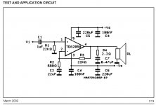
*The larger figure, 4.7uF will operate the amplifier full bandwidth; however, you'd also need to increase the size of the NFB cap (C2) by the same proportion--If C1 is 4.7uF then C2 is 100uF.
*The smaller, 1uF (with 22uF at the NFB) can run full bandwidth if you multiply the values of R1, R2, and R3 by 4.55 times (22k * 4.55 = 100k).
Speaker output zobel:
For your C7, it specs only for polyester (because of the typically high ESR).
*otherwise the 2.2R load of R4 could be increased to 5R or higher figure to use ceramic or polypropylene caps at the zobel.
Input filter caps (C1):
Nichicon ES 1uF is a solid performer, bipolar, so its "reversible" for more or less brightness.
The Elna Cerafine 4.7uF is also a solid performer (stripe towards source, normally).
*The larger figure, 4.7uF will operate the amplifier full bandwidth; however, you'd also need to increase the size of the NFB cap (C2) by the same proportion--If C1 is 4.7uF then C2 is 100uF.
*The smaller, 1uF (with 22uF at the NFB) can run full bandwidth if you multiply the values of R1, R2, and R3 by 4.55 times (22k * 4.55 = 100k).
Speaker output zobel:
For your C7, it specs only for polyester (because of the typically high ESR).
*otherwise the 2.2R load of R4 could be increased to 5R or higher figure to use ceramic or polypropylene caps at the zobel.
Last edited:
Thanks for the comments guys.
I went to chipamp.com to see what was used. I noticed they have a bipolar electrolytic for C2 on the LM1875 kit. I would suspect C2 to have as much influence on the signal quality as C1. Would it be all right to use a bipolar electrolytic as C1 then? Or has it been deemed that the C1 position has more influence over the sound. At the small cost of getting the bipolar, I will try both, but I was just wondering what everyone elses experience may have been.
I went to chipamp.com to see what was used. I noticed they have a bipolar electrolytic for C2 on the LM1875 kit. I would suspect C2 to have as much influence on the signal quality as C1. Would it be all right to use a bipolar electrolytic as C1 then? Or has it been deemed that the C1 position has more influence over the sound. At the small cost of getting the bipolar, I will try both, but I was just wondering what everyone elses experience may have been.
C1 has the biggest influence. C2 is the second most influential. The choice of a bipolar capacitor for C2 is necessary, because the feedback filter's high pass frequency is higher than the input filter's. A 22 µF film capacitor in that place would be inadequately expensive and big, but you can achieve a sonic improvement in that place, by putting a small film capacitor in parallel to C2.
I found my LM1875 board and tested it again. DC offset is less than 1mV on my DMM. If you short the capacitor C2 the offset goes up to 49mV ( L ch) and 52 mV ( R ch ). This is still OK. After the amp warmed up ( about 30 mins ) the off set was 51 and 54mV respectively.
After playing music very loud for 30 minutes and the heat sink was too hot to touch continuously ( around 55 deg C ) the offset was 57mV and 62 mV respectively. Still OK though not a great figure. But if your C2 is not a 'great' cap then it might be better to run it dc connected and find the sound improving considerably.
However I'm not sure what your input and feedback resistors are.If they are low values then the offset will also be low. If you remove C2 ensure that C1 is present.Make sure you start off with C2 present and when you decide to short it out , take offset measurements with the speakers disconnected. You could also use a 1.5 amp fuse in series with the speakers while testing. Might save your speakers if you do something silly initially.
As I was almost done listening to the amp the loosely connected speaker ground slipped out and touched the incoming power supply pin and blew the chip !
This is a very good chip amp !
C2 and R3 form a high-pass filter. The bigger C2, the lower is the roll-off frequency. It does not actually increase the bass, but determines how low it goes, just like R2 and C1. A side effect is that the lower the filter frequency, the less phase turn you get in the audio band. Phase turn is usually considered to worsen the sonic performance.
C1: Definitely polypropylene
C2: I would prefer polypropylene, but a quality electrolytic such as Nichicon KZ with a 100 nF polypropylene in parallel would work too.
C3, C4, C7: Polypropylene or MKT would be my choice.
C5, C6: Low-ESR electrolytic.
Actually, I would redesign the circuit to use a DC servo. That would get rid of C1, C2 so you don't have caps in the signal path. And with a DC servo, I would limit the caps to 1 uF, thus, making it possible to use quality ceramic caps or PP if I wanted to get fancy. LF411 or LMV841 look like good candidates for a DC servo circuit.
As others have said already: C1 is where you want to spend your money. Then C2. The rest are secondary.
~Tom
Again, thanks for the replies guys. I might try it without the input and feedback caps then. I was thinking more about it and I had planned to build this for a guitar amp anyways. From the pedals I have seen, most are capacitor coupled to the output inside the pedal, so there shouldn't be much of any offset coming out of the pedal and into the amp.
Guitar amp application ? Then why all this fuss about 'best' caps ?
In that case I think you will probably never find any significant difference in following all the recommendations that have been given on this thread.
In your application you BETTER use an input cap and the feedback cap ( C1 and C2 ).
IMHO you can get away very well with a low cost polyester cap at the input and any electrolytic cap at the C2 position. Others can be low cost polyester and electrolytics.
Parallel polyester/polyprop on C2 will not improve the sound of your guitar. I doubt you will hear any difference between polyprop or polyester at C1 if the signal source is a guitar. Don't get carried away and get expensive caps in this application.
Sorry guys, I didn't reviel my full plans. I was planning on building on for my guitar, which would come first and then two for my stereo after that. That was the reason for all the capacitor questions. They were meant for the stereo modules.
For guitar amp, you can omit C2 (just use a wire or a 3.3 ohm 1/2w carbon resistor), and use an Output cap (2200uF or larger) plus a fuse, both in series with the speaker, for really effective speaker protection. Rigged that way, even an amp in practically worn out condition will keep right on playing like it was new. It also helps prevent damage from pushing the little amp too hard in guitar use.
Examples:
Nichicon PR 2200uF 63v
Mallory LP332M050C5P3
and of course many other models work for that.
I'm saying that you can easily drop the load on DC instead of dropping the gain on DC (assuming that you have an input filter cap "c1" in either case).
P.S.
Pacificblue's example of bypassing electrolytic caps with small film caps can work very well. Even really cheap polyester caps can do it nicely. Depending on the capacitance value and several other things, there is much variety available at a low cost.
P.P.S.
The caps at the power circuit can possibly matter twice as much as your input filter cap (c1). The wave of the speaker ends up in the power circuit, you know.
The greatest variety is, perhaps, the size of the caps that are directly at the chip amp (assuming that the amp has a nice big separate power supply board, you can use 100uF 220uF, 330uF, 470uF, or 680uF caps at the amplifier board).
You can also use about a 3.3uF (a step smaller or a step larger is fine) film cap from V+ to V- at the amplifier board--some luck with that makes noise go out of style fast.
Also, a regulated power supply can sometimes make a surprising difference in clarity, and that is an option that you might want to explore for your stereo system.
The point of this bit, is that instead of running out of "hot-rodding" options (upgrades?) at the audio circuit, see what options you have at the power circuit.
I hope it gives you some ideas.
I picked out the caps I was thinking of using. I choose them as if it was for the guitar amp setup.
C1: 2.2uF Panasonic Bipolar
C2: 22uF Panasonic Bipolar
C3, C4, C7: Epcos 0.1uF metallized polyester
C5, C6: Panasonic FC 100uF 63V electrolytic
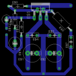
I link a picture of a board I made up in Eagle. Please don't laugh at it. I am just learning Eagle. Does the layout look acceptable?
Thanks.
C1: 2.2uF Panasonic Bipolar
C2: 22uF Panasonic Bipolar
C3, C4, C7: Epcos 0.1uF metallized polyester
C5, C6: Panasonic FC 100uF 63V electrolytic
I link a picture of a board I made up in Eagle. Please don't laugh at it. I am just learning Eagle. Does the layout look acceptable?
Thanks.
Attachments
C1: 2.2uF Panasonic Bipolar
C2: 22uF Panasonic Bipolar
C3, C4, C7: Epcos 0.1uF metallized polyester
C5, C6: Panasonic FC 100uF 63V electrolytic
Sounds OK. Why 63V electrolytics ? Anything above 25 V would do. Like 35V or 50 V. But higher voltage ratings are fine. They are just bigger and more expensive. Supply decoupling could be plain yellow coloured boxed 63V 0.1uF . Epcos would be bigger and far more expensive.
- Status
- This old topic is closed. If you want to reopen this topic, contact a moderator using the "Report Post" button.
- Home
- Amplifiers
- Chip Amps
- Capacitor types in chip amp (TDA2050)