Almost two years ago I started building a LM3886 based chipamp, and somehow in the intervening years the project got boxed up and set to the side. Then a few weeks ago I got re-motivated on this project and am now almost finished with it. The power supplies are finished and I'm just buttoning up the amplifier section.
The layout is definitely non-standard and contains two "mono-blocks" combined into three separate chassis. They are "mono-blocks" in the sense that each channel has its own power supply and there are no electrical connections between the channels other than the chassis grounds. Each power supply is in a dedicated case and the two amplifier channels are in a third case.
Here's the original thread related to toroid choice and power supply voltages as relates to speaker impedance.
http://www.diyaudio.com/forums/chip-amps/115901-toroid-question-lm3886-photos.html
And more excitingly here are some pictures of the progress, additional photos are at the following link:
Blank Photos :: LM3886 Chipamp
Braided power cable for the dc and ground connections between the power supplies and the amplifiers. The wires are salvaged from spare computer power cables (have a ton of them at work).

A completed power supply board with inputs from the toriod on the front and dc outputs on the rear.

Smoke testing a power supply using the lightbulb method.

A/C side of a power supply showing the IEC connector, fuse, chassis ground, switch, and primaries side of the toroid.

The other side of the power supply showing the toroid secondaries and ps board mounted on custom 3/8" delrin standoffs.

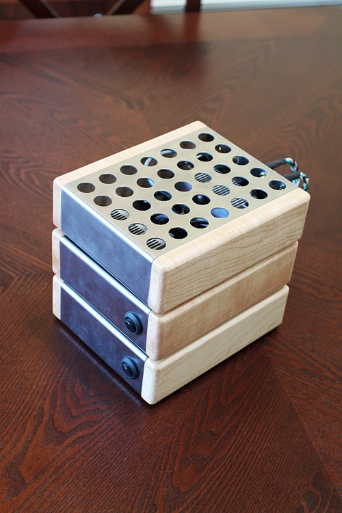
The mostly finished power supplies from the top. The enclosures are made of stainless steel which is a huge pain to work with, I recommend avoiding it if at all possible. The sides are solid maple which is also a difficult material to work with. Obviously the U/L would frown on the holes in the top, I'm thinking of possibly putting some metal mesh in to block the holes.

Rear view. I'm debating if I should clear coat the maple or stain it a darker color. Any opinions?

Fronts.

For the LM3886 heat sinks I cut a large computer heatsink in half. It is designed to dissapate a huge amount of heat off of a cpu, hopefully it will keep the temps reasonable with the chipamp. The base is almost 1/2" of solid aluminum and the fins are about 1.5" long.

Mocking up the amplifier chassis. Each board has a dedicated heatsink. All power and signal connections are on the rear panel. More pictures to come as I make progress.

DiyAudio.com was a great resource in researching this project, hopefully this writeup will assist someone else in the future.
- Matt
The layout is definitely non-standard and contains two "mono-blocks" combined into three separate chassis. They are "mono-blocks" in the sense that each channel has its own power supply and there are no electrical connections between the channels other than the chassis grounds. Each power supply is in a dedicated case and the two amplifier channels are in a third case.
Here's the original thread related to toroid choice and power supply voltages as relates to speaker impedance.
http://www.diyaudio.com/forums/chip-amps/115901-toroid-question-lm3886-photos.html
And more excitingly here are some pictures of the progress, additional photos are at the following link:
Blank Photos :: LM3886 Chipamp
Braided power cable for the dc and ground connections between the power supplies and the amplifiers. The wires are salvaged from spare computer power cables (have a ton of them at work).
A completed power supply board with inputs from the toriod on the front and dc outputs on the rear.
Smoke testing a power supply using the lightbulb method.
A/C side of a power supply showing the IEC connector, fuse, chassis ground, switch, and primaries side of the toroid.
The other side of the power supply showing the toroid secondaries and ps board mounted on custom 3/8" delrin standoffs.
The mostly finished power supplies from the top. The enclosures are made of stainless steel which is a huge pain to work with, I recommend avoiding it if at all possible. The sides are solid maple which is also a difficult material to work with. Obviously the U/L would frown on the holes in the top, I'm thinking of possibly putting some metal mesh in to block the holes.
Rear view. I'm debating if I should clear coat the maple or stain it a darker color. Any opinions?
Fronts.
For the LM3886 heat sinks I cut a large computer heatsink in half. It is designed to dissapate a huge amount of heat off of a cpu, hopefully it will keep the temps reasonable with the chipamp. The base is almost 1/2" of solid aluminum and the fins are about 1.5" long.
Mocking up the amplifier chassis. Each board has a dedicated heatsink. All power and signal connections are on the rear panel. More pictures to come as I make progress.
DiyAudio.com was a great resource in researching this project, hopefully this writeup will assist someone else in the future.
- Matt
Matt they look great. I really like your enclosures, not the typical approach. Are you impressed with the sound?
Matt they look great. I really like your enclosures, not the typical approach. Are you impressed with the sound?
I'm really looking forward to finishing them so I can do a full review. The last time they made any noise was in early 2008 when I was mocking everything up, and I remember being quite impressed with the sound quality at that time.
- Matt
I really like your design and the usage of for example the cpu heatsink.
Hopefully the sound will be impressive this time around aswell.
-
Kolbjørn
Hopefully the sound will be impressive this time around aswell.
-
Kolbjørn
The amplifiers are now electrically finished and playing music, all that is left is to clear-coat the maple side panels. So far I've only done initial listening, but I'm very happy with the sound. Here are some more pictures:
Amp boards bolted to heat sinks and input and outputs wired up.

Testing the amp section.

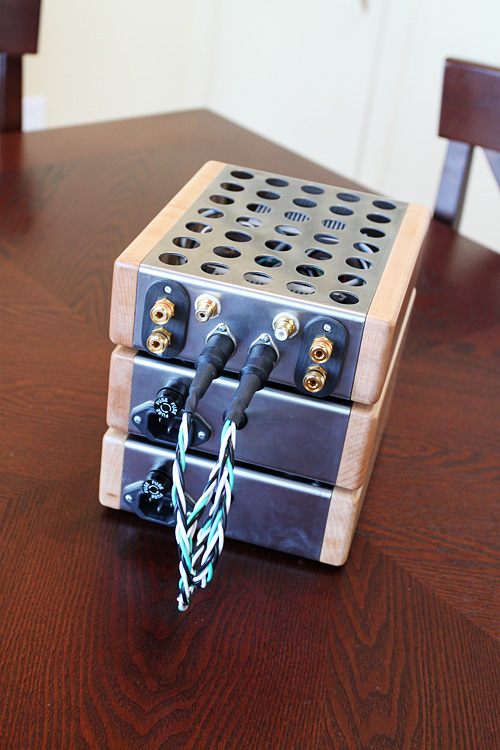
Rear of the amp module.

Inside of the amp module, space is tight but everything fits.

Both power supplies and the amp module.

Top view.

I think the three modules look better stacked, they take a lot less surface space this way. The sides still need to be sanded and finished.


- Matt
Amp boards bolted to heat sinks and input and outputs wired up.
Testing the amp section.
Rear of the amp module.
Inside of the amp module, space is tight but everything fits.
Both power supplies and the amp module.
Top view.
I think the three modules look better stacked, they take a lot less surface space this way. The sides still need to be sanded and finished.
- Matt
Looks great. I'm glad you didn't stain the maple, it's such a beautiful tone. I'd just finish them with tung oil, as they won't be handled much.
Looks great. I'm glad you didn't stain the maple, it's such a beautiful tone. I'd just finish them with tung oil, as they won't be handled much.
Thanks! I stained a couple test pieces and wasn't happy with the outcome. I was planning to just use a clear poly coating on them and hadn't though of tung oil. Will tung oil yellow considerably over time? Is the benefit that it brings out the grain better? I'll definitely have to do some research.
- Matt
To last longer, you need big air intake holes underneath the fins of those heatsinks.
Air "inlet"
Air "inlet"
Daniel,
Thank you for the suggestion, a set of bottom vent holes are definitely on the list so that convective cooling works properly.
- Matt
Thank you for the suggestion, a set of bottom vent holes are definitely on the list so that convective cooling works properly.
- Matt
A possibility, but by no means a suggestion to do so, is that there is some tonality control easily available with that kit.
Those 100uF at the amplifier boards, for V+ and V- . . .
You can parallel another pair of 100uF's or. . .
You have the option of replacing the 100uF's with 220uF, 330uF, or 470uF
and
You also have the option of using One 2.2uF, 3.3uF, or 4.7uF big polyester tweeter cap connected from V+ to V- (which is a slight "sink the mids" arrangement and it also blocks noises).
P.S.
The kit's output zobel has the erroneous combination of a small value resistor with a polypropylene cap. That can "dim" your treble, exposing a lot of midrange. You can either increase the resistor value, or its ever so simple to replace that polypropylene cap with a 220nF (0.22uF) or 100nF (0.1uF) green polyester dip cap from your local Radio Shack store (for example). Using an even smaller value is still yet better than omission.
Polyester has a typically high internal resistance, and the national semiconductor datasheet meant to use that type of cap for the speaker output zobel (RC) which is a customary practice. The only way to tell on that particular document is that the resistor figure looks insane. They were counting on the added resistance within an inexpensive polyester cap (the normal thing to use for the amplifier's speaker zobel).
Supporting optional types of caps (like polypro or ceramic) at the speaker zobel would need a larger resistor value, else there is possibly too much load. You can fix this by replacing either the resistor or the cap in the speaker output zobel.
The amps are now finished, I applied 6 coats of tung oil to the sides and am very happy with the results. Unfortunately the pictures below don't do the finish much justice.
After listening to these for a while I'm quite impressed with the midrange clarity and the bass control, the only thing missing is a sense of "openness" in the treble. Cymballs lack shimmer and don't sound very realistic. I'm wondering if Daniel's suggestion regarding the output zobel capacitor will help with this, time to experiment.
- Matt
You mention that the solid maple was a pain to work with. What made it a pain and how it different from working with other types of wood? I'm considering using maple for the chassis of my next tube amp.
~Tom
~Tom
Hello Matt, nice looking work you have there. Hope the sound turns out as good as the appearance. One thing I can recommend is to try and clear coat the stainless steel. I work with high polish stainless like that a lot. It's a bear to keep fingerprints and smudge marks off of. You will likely be cleaning it constantly, and polishing, if you don't do a clear coat.
Peace,
Dave
Peace,
Dave
The amps are now finished, I applied 6 coats of tung oil to the sides and am very happy with the results. Unfortunately the pictures below don't do the finish much justice.
After listening to these for a while I'm quite impressed with the midrange clarity and the bass control, the only thing missing is a sense of "openness" in the treble. Cymballs lack shimmer and don't sound very realistic. I'm wondering if Daniel's suggestion regarding the output zobel capacitor will help with this, time to experiment.
I favor several mods that have only a slight effect.
So, while using the normal and expected piece in the speaker outbut zobel will help the problem you described, unfortunately it won't help to the extent described.
Add 2 more slight mods:
(mids) One 4.7uF big polyester tweeter cap from V+ to V- at the output of the power supply board (effect: cuts some noise out of the mids, putting the mids presentation closer to the speaker instead of way out in front).
*This is similar to the sidenote in the 2005 CarlosFM chipamp power supply schematic.
(treble) With that amp kit, you'll just have to fake the treble and that's a small value high efficiency ceramic (range 10nF to 220nF) in parallel with your input filter cap (effect: force more upper treble into the amp). The size and efficiency to select for your bypass cap will vary for each amp, and you may like polyester or polypro bypass cap better.
*Bypass cap is a common practice for the problem you've described and since the amp is popular, maybe you can find some specific recommendations from others who own this amp. Specific parts with a "known good" performance, regardless of price, will always outperform botique parts.
In combination, that's:
(zobel-use polyester cap) allow more upper treble to pass
(ps-add a filter) sink the mids slightly and maybe clarify
(input-add a bypass cap) last step = give the upper treble a shove.
And, in combination, in that order, the little mods can make a slight alteration in the presentation from your amplifier. Maybe it will be enough to hear the cymbals.
Daniel, if one increases the value of the Zobel resistor, what value do you recommend increasing it to? Doubling it? I have one of these kits and I'd prefer changing the resistor in the Zobel to changing the capacitor.
Daniel, if one increases the value of the Zobel resistor, what value do you recommend increasing it to? Doubling it? I have one of these kits and I'd prefer changing the resistor in the Zobel to changing the capacitor.
With the high efficiency cap at the zobel? 4, 6 or 8 ohms resistor. They seem to be favoring 6. That would be very close to the efficiency difference in a "made for filter cap" versus the high efficiency polypro cap.
They (4R, 6R, 8R) are also all corresponding to an expected amount of load for a speaker for LM3886.
Other details:
Smallest value 3.3R, largest 10R, and anything in that range that "sounds nice" is probably just right.
If the resistor is hot, the amp is less than stable, in which case you could review star grounding and add part "CC" from National Semiconductor's LM3886.pdf.
However. . .
The other half of the Thiele/Small output filter was not included with the kit, but that's 0.7uH//10R in series with the speaker jack. See National Semiconductor's LM3886.pdf.
Thanks for the information. I'll probably try the 6 ohm resistor. Do you recommend the 0.7uH//10R series filter? The datasheet suggests it may be useful for long runs on speaker cable, but I'm not sure that's applicable in my case.
Historical data suggests favorable reviews from LM3886 owners using the output inductor//resistor.
The output zobel increases the load at pitches above the audio band and in compensation the output inductor//resistor decreases the load at pitches above the audio band (very useful). These (4) parts work together to form the theile/small network. As shipped, the kit is incomplete.
Last edited:
- Status
- Not open for further replies.
- Home
- Amplifiers
- Chip Amps
- LM3886 Chipamp Project Resurrected