hi! so this is my first diy amp, and i decided to use lm3886 because of its great audio quality....
I made 2 differets pcbs with one Lm3886 and i tried each one and every LM3886 work! suond is good... I really like that...
now, the two pcbs work and I want to do Parallel configuration 100W on 4 Ohms....
but there is a problem... when i connect two LM3886 in parallel on 4Ohms load they go in protection mode and they overheath...
I 've checked wirings and they are rights, the heath sink is too big for 2xlm3886 so , I haven't got power dissipation problems....
what is the problem??? i don't understad why each pcb work in single mode, and don't work in Parallel mode... help me!!!
thanks and sorry for my bad english...
Do you have current sharing resistors on the outputs? Are you using 0.1% resistors in the feedback loop?
Your problems sound like one chipamp is driving the other. 0.1% resistors are not strictly necessary, I use 1% resistors and a larger output resistor (0.25 ohm) to balance the chipamp out. But output resistors are critical, the amp will not function without them.
Your problems sound like one chipamp is driving the other. 0.1% resistors are not strictly necessary, I use 1% resistors and a larger output resistor (0.25 ohm) to balance the chipamp out. But output resistors are critical, the amp will not function without them.
the gain of both amps must be matched. that is why you need the 0.1% resistors shown for PA100.
The input offset current of the two amps may interact with each other if you simply parallel them. Do you have DC blocking caps on the inputs of both chipamps?
The 0rX output resistors are a must.
Although the AN1192 does not show the output Zobel, I believe it is necessary and further that every chipamp needs the Zobel on it's output.
the gain of both amps must be matched. that is why you need the 0.1% resistors shown for PA100.
The input offset current of the two amps may interact with each other if you simply parallel them. Do you have DC blocking caps on the inputs of both chipamps?
The 0rX output resistors are a must.
Although the AN1192 does not show the output Zobel, I believe it is necessary and further that every chipamp needs the Zobel on it's output.
yes, i've used the zobel on output, and DC blocking caps, but the problem is: if i turn on one LM3886 in "single mode" (not parallel) it work!!!! and if i do a parallel configuration there is the problem...
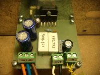
i post the pcb image
Attachments
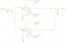
When you make a schematic you NEED to make the little dots where you want the wires to connect. Now it's pretty much guesswork as you use the dots somewhere and other obvious places not.
Eagle will warn you about it if you do a Electrical Rule Check(Tools->Erc), I find its a good thing to run that now and again, especially if one change something.
Eagle will warn you about it if you do a Electrical Rule Check(Tools->Erc), I find its a good thing to run that now and again, especially if one change something.
When you make a schematic you NEED to make the little dots where you want the wires to connect. Now it's pretty much guesswork as you use the dots somewhere and other obvious places not.
Eagle will warn you about it if you do a Electrical Rule Check(Tools->Erc), I find its a good thing to run that now and again, especially if one change something.
yes, but only parallel configuration don't work, single config, with one lm3886 on 4 Ohm works perfectly!!
Take out C2 and C5 and see, if the parallel configuration becomes stable without them.
so, i've just tried to take out C2 and C5, but i have the same problem, lm3886s goin protection mode and they overheat! what is the problem???
From what I see, the layout doesn't match the schematic, it looks like you made two sepparate boards in the same way. My guess is that one of the input wires is connected in the wrong way. making one of the LMs to keep the output on 0 while the other one tries to amplify the signal and therefore its output is shorted to ground through the other chip.
From what I see, the layout doesn't match the schematic, it looks like you made two sepparate boards in the same way. My guess is that one of the input wires is connected in the wrong way. making one of the LMs to keep the output on 0 while the other one tries to amplify the signal and therefore its output is shorted to ground through the other chip.
Maybe, it could be... but i've followed datasheet istruction. I've done this schematic
From what I see, the layout doesn't match the schematic, it looks like you made two sepparate boards in the same way. My guess is that one of the input wires is connected in the wrong way. making one of the LMs to keep the output on 0 while the other one tries to amplify the signal and therefore its output is shorted to ground through the other chip.
so, maybe have I invert input signal??? change input signal with Ground in one LM3886??
change input signal with Ground in one LM3886??
Not necessary. It would be better to identify the signal wires with a multimeter rather than invert them randomly.
Oscillation could be the problem. Since you have the Zobel network on the PCB, you connect two in parallel, when you put the two amplifiers in parallel. You could try to disconnect one of the Zobel networks or to increase the resistor values. Something between 4R7 and 10R could work. Maybe you even have to do both things. If you had an oscilloscope you could watch the effect. Maybe your set-up even works better with no Zobel at all.
By the way, the resistors in a Zobel network should ideally be low-inductive. The ones in your photo seem to be wire-wound, which is exactly the opposite. Did you notice that National recommends 0,25 W resistors in that place?
By the way, the resistors in a Zobel network should ideally be low-inductive. The ones in your photo seem to be wire-wound, which is exactly the opposite. Did you notice that National recommends 0,25 W resistors in that place?
Oscillation could be the problem. Since you have the Zobel network on the PCB, you connect two in parallel, when you put the two amplifiers in parallel. You could try to disconnect one of the Zobel networks or to increase the resistor values. Something between 4R7 and 10R could work. Maybe you even have to do both things. If you had an oscilloscope you could watch the effect. Maybe your set-up even works better with no Zobel at all.
By the way, the resistors in a Zobel network should ideally be low-inductive. The ones in your photo seem to be wire-wound, which is exactly the opposite. Did you notice that National recommends 0,25 W resistors in that place?
i'm apologize, but i haven't got an oscilloscope,but i'll try to change zobel network values... 2 days ago, I tested amp without zobel network, but i've got the same problem... so, i'll try to increase zobel resistor value, but i don't think that's resolve the problem...
Last edited:
No need to apologize. An oscilloscope is not a common household appliance.
If you increase the Zobel resistance, try normal metal-oxide resistors to make sure the wire-wound's inductance does not create a resonant circuit with the 100 nF capacitor. The easiest thing is to just take one of the resistors out and see, if it improves anything.
If you increase the Zobel resistance, try normal metal-oxide resistors to make sure the wire-wound's inductance does not create a resonant circuit with the 100 nF capacitor. The easiest thing is to just take one of the resistors out and see, if it improves anything.
- Status
- This old topic is closed. If you want to reopen this topic, contact a moderator using the "Report Post" button.
- Home
- Amplifiers
- Chip Amps
- LM3886 PA100 Problem